It is often said in plants that a HVAC system which is delivering the desired temperature and Relative Humidity is working fine. Is it a complete statement? Although the desired parameters of HVAC system are met, the plant managers do have a complaint that the specific energy consumption (That is Electrical energy consumed per product produced) is higher than the other plants of similar size and facility. The following paragraphs are about one such experience we had while auditing a plant.
One of the leading auto components manufacturing plant which has got multiple plants in India had recently constructed a plant with state-of-art facility. The process demands controlled environment, that is controlled humidity going up to 34% RH in certain shops and 50% RH at other parts of the plant. This means there is a huge capex involved in the form of HVAC system. Although, all the process parameters are perfectly met, the plant management still had worries as the specific power consumption per product is considerably higher when compared to other plants of their own group. This is where we came into picture to support them in analyzing the system.
The HVAC system contributes close to 48% of the energy consumption of the plant. This includes, centrifugal fans, centrifugal pumps, chillers, cooling towers etc. For the moment we will be discussing about the centrifugal fans which are used in Air handling units (AHU), Air washer units or the evaporative cooling system, Centralized exhaust system. Let us discuss about a case study which reflects the majority.
Case Study:
Equipment: Centralized exhaust system
Equipment Specification
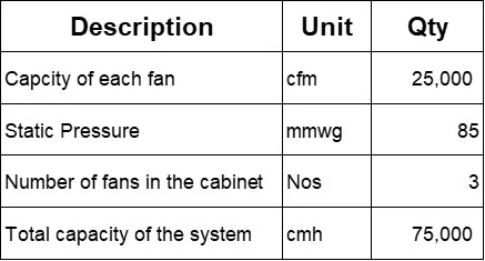
Table 1
Audit Observation
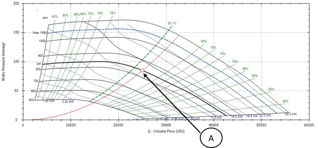
The actual parameters of the exhaust system that is volumetric flow rate and static pressure were measured with the help of Pitot tube. Please refer Fig 1 for the performance curve at the selected parameters. Refer Point A
It was observed that the actual static pressure is much less than the selected static pressure. This has resulted in a considerable drop in efficiency. Please refer fig 2 (performance curve).
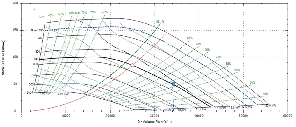
The blue dotted line is the duty point at which the fan is running currently. It can be seen from the fig 2 that the efficiency of the fan has dropped from 82% to 67%. This loss in efficiency will obviously lead to loss of energy.
Now the natural question is why the operating point got shifted. To answer this, we need to go to our drawing bords. While designing the system, after calculating the static pressure required, designers generally tend to add factor of safety. Even while designing the ducts, they keep factor of safety and increases the size of the duct more than the required size. Prima-facia, one can think, what’s wrong in adding factor of safety or what’s wrong in increasing the duct size or increasing the static pressure more than what is required. One may even think that it should be better if we slightly oversize the system, that the size of duct and static pressure.
This is where the actual problem starts. If we over size the duct dimensions, for a given volumetric flowrate of air, the required static pressure will come down than estimated. Same way, if we add factor of safety to the static pressure at the design stage, in reality (like this case study), the actual static pressure will be less than what was selected. These two factors will lead to lesser static pressure. In this case, the selected static pressure is 85mmwg, whereas the measure or the actual static pressure is 50mmwg. The change in static pressure will alter the operating point or the duty point of the fan as can be seen in the fig 2 (performance curve). Hence it evident that adding factor of safety unnecessarily will lead to inefficient performance of the fan. In this case, the power consumed by the system (that all combination of all three fan in the cabinet) was 37.3kW. After implementing our countermeasure, the power came down to 21.4kW, which is 42% reduction in energy.
It can be inferred that although the plant and equipment are new, still there were potential to reduce around 40% of energy. This is only a tip of an iceberg. If we have a detailed analysis, we can find many such opportunities.
Now, let’s understand how to eliminate inefficiency.
It is a general practice in India that the designs are being made by a company and executed by different companies. At the concept stage, the layouts are not finalized. In most cases not even to the level of 70%. Since the layouts are not finalized, the designers are forced to add factor of safety. Moreover, the feedback of the performance of the fan are not reaching the designer once it is commissioned and hence the chances of correcting in future projects becomes bleak. To avoid we need to do the following
- Finalizing the layout at design stage to the extent of 90%
- Static pressures should be calculated with due diligence and should be approximated based on past experience
- Sizing of duct should be optimal
- Feedback after commissioning the system should considered and if it calls for any modification, the same need to be addressed.
Moreover, it is advisable to go with one company which participates in the entire process, that is from the stage of concept till commissioning and the loops should closed at every possible instance.