In HVAC/R equipment design, every uncertainty at the CAD stage transforms into real-world risks later. That’s why forward-thinking manufacturers are now embedding simulation-readiness from the start—not waiting until prototype failure. Finite Element Analysis (FEA) has emerged as a critical tool for engineers seeking to predict and optimize material behavior under complex stresses, ensuring design resilience and safety long before physical prototypes are built.
Table of Contents:
- The Traditional Risk: Waiting Until It’s Too Late
- Understanding FEA: A Proactive Approach
- Simulation-Led Design: A Smarter Way Forward
- Where FEA Makes the Biggest Difference
- CAD Integration and Design Process
- Ensuring Reliability: How We Leverage FEA
- Implementation Challenges and Solutions
- Conclusion
The Traditional Risk: Waiting Until It’s Too Late
Historically, HVAC/R equipment designs followed a “build first, fix later” cycle:
- Prototypes built based on best-guess designs
- Physical testing revealed weak points
- Redesigns led to costly delays and rework
This approach is now outdated. In today’s competitive environment where speed to market, first-time quality, and regulatory compliance define success, waiting for failure is simply not an option. Every design flaw discovered late in development dramatically increases costs and delays market entry—risks that modern manufacturers can no longer afford to take.
Understanding FEA: A Proactive Approach
This methodology transforms complex engineering problems into solvable mathematical models, by segmenting intricate structures into smaller, manageable elements. This approach allows engineers to:
- Predict Material Behavior: Simulate how materials respond to varying mechanical loads, thermal stresses, and vibrations
- Identify Weak Points: Locate potential failure areas before any physical prototypes are built
- Optimize Designs: Engineer components to achieve high strength with reduced material consumption
- Validate Performance: Verify that the designs comply with—and ideally surpass—safety standards in any operational scenario
The FEA process involves several key steps:
- Geometry Creation: Developing accurate 3D models through using CAD to capture all critical features
- Material Property Definition: Assigning accurate physical characteristics to each component
- Mesh Generation: Dividing the geometry into finite elements for numerical analysis of physical behavior
- Boundary Condition Application: Defining how components interact with their environment
- Solution Calculation: Computing stresses, strains, and deformations present throughout the model
- Results Analysis: Interpreting outputs to identify opportunities for design optimization
At its mathematical core, FEA solves complex partial differential equations that would be impossible to calculate manually. This methodical approach transforms uncertainty into confidence, allowing engineers to make informed decisions before committing to physical prototypes.
Simulation-Led Design: A Smarter HVAC/R Way Forward
Forward-thinking HVAC/R OEMs are now shifting toward designing for validation, not just appearance. This fundamental change in approach recognizes that simulation isn’t about making engineering fancy—it’s about catching costly mistakes before they hit the production line.
SolidWorks design and other advanced CAD platforms now integrate seamlessly with FEA tools, creating a continuous workflow where design and validation happen in parallel rather than sequence. This integration allows engineers to:
- Test multiple design concepts virtually before selecting the optimal approach
- Identify and address potential issues during the design phase
- Reduce the number of physical prototypes required
- Accelerate the overall development timeline
The result is a more efficient development process that produces higher-quality designs with fewer iterations and lower costs. For HVAC equipment design specifically, this approach ensures that performance specifications are met from the first physical prototype, dramatically reducing development time and costs.
At Asset-Eyes, we integrate simulation readiness into every design handoff, helping our clients move faster, with more certainty, and less risk.
Where FEA Makes the Biggest Difference HVAC/R
Unlike firms offering end-to-end CFD and thermal modeling, Asset-Eyes focuses on two critical, high-stakes areas for HVAC/R manufacturers:
1. Compact System Design Validation
Challenge: As equipment footprints shrink to meet modular and retrofit demands, maintaining airflow, efficiency, and serviceability becomes increasingly difficult.
How Asset-Eyes Helps:
- Our HVAC CAD drafting services ensure that even the most compact systems meet performance requirements
- We validate that reduced-size components maintain structural integrity
- We ensure thermal stresses remain within acceptable limits despite tighter packaging
Industrial ventilation system design and evaporative cooling system design particularly benefit from this analysis, as these systems often face significant space constraints while needing to maintain optimal performance.
2. Failure Mode Anticipation (Structural FEA Readiness)
Challenge: Load stresses, vibrations, and transport shocks can silently weaken HVAC/R systems, leading to field failures and warranty costs.
How Asset-Eyes Helps:
- We build models designed for structural simulation (FEA), ensuring clients can validate mechanical robustness early
- Our approach predicts how components will respond to mechanical loads and vibration
- We identify high-stress areas that may experience premature fatigue
- We simulate extreme conditions that would be difficult to test physically
For specialized applications like electrical control panel design and motor control panel design, FEA ensures that enclosures and mounting systems can withstand the vibration and thermal stresses inherent in HVAC/R operations. Similarly, industrial exhaust system design benefits from this analysis to ensure components can handle high temperatures and potentially corrosive environments.
CAD Integration and Design Process
Modern FEA implementation relies on seamless integration with CAD systems, creating a unified workflow that enhances efficiency and accuracy:
CAD Model Preparation: Quality CAD drawing services ensure that models are structured for simulation compatibility from the beginning. This includes:
- Appropriate simplification of non-critical features
- Proper definition of mating surfaces and interfaces
- Accurate material assignments
- Parametric design features that facilitate optimization
SolidWorks to FEA Workflow: SolidWorks design and SolidWorks drafting services play a crucial role in creating simulation-ready models:
- Initial concept development in SolidWorks
- Model preparation for FEA compatibility
- Direct transfer to FEA software without data loss
- Analysis and identification of optimization opportunities
- Design modifications in SolidWorks based on FEA results
- Final validation and documentation
2D Documentation Integration: While 3D models drive the simulation, 2D drafting in SolidWorks remains essential for manufacturing documentation:
- Critical stress areas identified in FEA are highlighted in 2D drawings
- Manufacturing tolerances are adjusted based on stress sensitivity analysis
- Assembly instructions incorporate insights from structural analysis
- General assembly drawing captures the validated design intent
This integrated approach ensures that insights from stress analysis directly inform both the design evolution and manufacturing documentation, creating a continuous improvement loop that results in optimized products.
Ensuring Reliability: How We Leverage FEA HVAC/R
We are not simply a simulation vendor—we are the bridge between conceptual design and confident production. At Asset-Eyes, we understand the critical importance of material integrity in HVAC/R equipment performance.
We have the capabilities to perform detailed FEA analysis as one of our core service offerings. Our approach combines advanced simulation techniques with practical HVAC/R industry knowledge, delivering actionable insights that improve equipment performance.
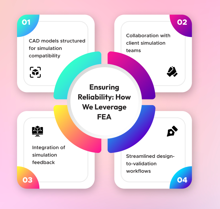
Here’s how we plug into your process:
- CAD models structured for simulation compatibility
- Collaboration with client simulation teams for faster model iterations
- Integration of simulation feedback into final manufacturing drawings and documentation
- Streamlined design-to-validation workflows that reduce project timelines
Implementation Challenges and Solutions
Despite its power, implementing FEA comes with several challenges that must be addressed:
Computational Requirements: Complex models require significant computing resources. Modern solutions include cloud-based computing options that provide scalable resources without massive hardware investments.
Model Validation: Ensuring simulation accuracy requires validation against real-world performance. This can be addressed through strategic physical testing of critical components to confirm FEA predictions align with actual behavior.
Expertise Requirements: Effective FEA demands specialized knowledge in both simulation techniques and HVAC/R applications. This challenge can be addressed through partnerships with experienced FEA service providers or targeted training programs for engineering staff.
Integration with Existing Workflows: Incorporating FEA into established design processes requires careful planning and coordination. Success depends on creating streamlined workflows where CAD drafting services and FEA analysis work in harmony rather than as separate functions.
Material Property Uncertainty: Material behavior can vary based on manufacturing processes and environmental conditions. Best practices include sensitivity analyses that evaluate performance across a range of material property values to ensure designs remain robust despite these variations.

Conclusion
In HVAC/R equipment manufacturing, the cost of finding design flaws late is too high to ignore. Embedding simulation-readiness into the early design stages is no longer optional—it’s essential for building equipment that meets today’s demands for efficiency, reliability, and compliance.
Finite Element Analysis has transformed from a specialized academic tool to an essential component of modern HVAC/R engineering. By providing deep insights into material behavior under complex loading conditions, FEA enables designs that are simultaneously more reliable, efficient, and cost-effective.
As HVAC/R systems continue to evolve toward greater efficiency and reliability demands, the role of advanced stress analysis will only grow in importance. Organizations that embrace these analytical capabilities position themselves at the forefront of industry innovation, delivering equipment that performs better, lasts longer, and operates more efficiently.
At Asset-Eyes, we ensure your HVAC/R equipment designs are not just ready for production, but engineered to perform in the real world.
Get Expert FEA Support for Your HVAC/R Projects
Ensure the reliability and longevity of your HVAC/R equipment with advanced material stress testing from Asset-Eyes. Our team of experienced engineers can help you optimize designs, troubleshoot existing equipment issues, and validate performance under a wide range of operating conditions.
Contact Us Today:
📞 +91 9840895134
Let our team help you harness the power of predictive analysis to optimize your HVAC/R equipment performance and reliability.