Are you confident your HVAC-R designs are maximizing value within your budget constraints? Small design choices often have significant impacts on material costs and long term efficiency, but they’re easy to miss when you’re focused on meeting deadlines and managing multiple projects.
At Asset-Eyes, we don’t just provide drafting services, we work as an extension of your team, bringing our specialized expertise to every project. Let’s look at some recent examples where this collaborative approach delivered real value beyond traditional drafting work.
Mechanical Case Study – HVAC-R
Case Study 1: Material Optimization for a Packaged Refrigeration System
When a client asked us to create drafting documentation for a packaged refrigeration system, the specifications called for an 8-inch base height. Most drafting services would simply follow these instructions without question. But our experienced team noticed something important: the base might be overbuilt for its purpose.
Instead of proceeding with the specifications as provided, we had a conversation with the client. Our team suggested that a 6-inch base might provide sufficient structural support while reducing material usage. To validate this idea, we conducted Finite Element Analysis (FEA) tests on both options.
The results confirmed our suspicions:
- The 8-inch base delivered a Factor of Safety (FOS) of approximately 1:4 – significantly higher than necessary
- The 6-inch alternative provided an FOS of 1:2 well within the ideal range for industrial refrigeration equipment
We presented both design options to the client with detailed documentation outlining the technical trade-offs. By highlighting how the 6-inch alternative met performance requirements without excess, we helped them make an informed decision grounded in engineering rationale.
We help optimize the entire design process from concept to production by implementing structured workflows that eliminate redundancies. Our CAD drawings services streamline documentation while maintaining precision.
Our process improvements include:
- Standardized design validation protocols
- Streamlined approval workflows
- Efficient documentation management
- Coordinated design review processes
While Asset-Eyes typically focuses exclusively on drafting services, this case represents an exception where our team’s experience allowed us to contribute to the design optimization process, creating additional value for our client.
The client achieved 25% material cost savings while maintaining optimal structural integrity. Our design revision helped the client cut material usage and avoid costly overdesign, contributing to overall savings in procurement and part preparation.
Case Study 2: Customizable P&ID for CO2 Refrigeration System
In another project, we partnered with a client to develop Piping and Instrumentation Diagrams (P&IDs) for a CO2 refrigeration system. The client faced a common challenge: each installation required slightly different equipment configurations based on facility requirements, yet creating new documentation for each project variation was time-consuming and inefficient.
Using our HVAC CAD drafting expertise, we created an innovative solution: a customizable P&ID system with intelligent components that could be quickly configured for different projects. The system included:
- Drop-down menus for selecting equipment like compressors, boilers, and heat exchangers
- Pre-configured options for different quantities of each component
- Standardized connection points ensuring system integrity across variations
- An optional heat reclamation module for facilities seeking energy efficiency
This “plug-and-play” approach transformed the client’s workflow. What previously required days of drafting work for each new configuration could now be accomplished in hours. The client could quickly generate accurate preliminary P&IDs during customer meetings and adapt to changing requirements on the fly.
The system proved particularly valuable when the client needed to respond to requests for facilities with specific energy recovery requirements. Using our customizable documentation, they could configure solutions with the heat reclamation module almost immediately dramatically improving their responsiveness to customer needs.
Our client success managers at Asset-Eyes maintain regular cadence meetings with both technical and business stakeholders, ensuring alignment as projects evolve. As a result, the client reduced P&ID configuration time from days to hours, significantly accelerating customer response times.
Electrical Case Study – HVAC-R
Our Focus On Enhancing Control Documentation for Improved Shop Floor Usability
At Asset-Eyes, our expertise extends beyond mechanical drafting to include specialized electrical system design. Just as our mechanical case studies demonstrated, our collaborative approach allows us to deliver value that goes well beyond traditional drafting services. A recent project with a CO2 refrigeration system manufacturer highlights how our electrical expertise translates into practical benefits for our clients.
Case Study 3: Making Control Drawings Shop-Floor Friendly with Ladder Logic
When collaborating with a client on a CO2 refrigeration project, our team was tasked with creating control drawings that would guide the manufacturing and installation process. Rather than simply recreating existing documentation, we identified an opportunity to significantly improve the usability of these critical drawings.
One key improvement our electrical engineering team made to the client’s original control drawing was the incorporation of ladder logic during the remapping process.
Ladder logic is a standardized way of representing control circuits in a format that resembles a ladder making it much easier to read and interpret, especially for technicians working on the shop floor. In this approach, all related components are organized in a clear, connected sequence, reducing clutter and improving readability.
Compared to the original diagram which had segmented or floating elements with minimal visual connection this layout significantly reduced confusion and interpretation time. It also minimized the need for visual “bubbles” and made better use of drawing space. The result was a cleaner, production-friendly control drawing that aligned more closely with how shop floor technicians actually interact with the system.
In addition to introducing ladder logic, the team also followed a logical flow in the structure of the control drawing. They began by mapping the power source, then showed how power was routed to the main controller, and finally illustrated the connections to the slave devices managed by the controller.
This step-by-step layout mirrors the actual flow of electricity and control in the system, making the drawing more intuitive for engineers and technicians. By following this sequence—power → controller → controlled devices the drawing not only became easier to understand but also aligned closely with how the system is wired and functions in real world operation.
Tangible Benefits for Production and Maintenance – HVAC-R
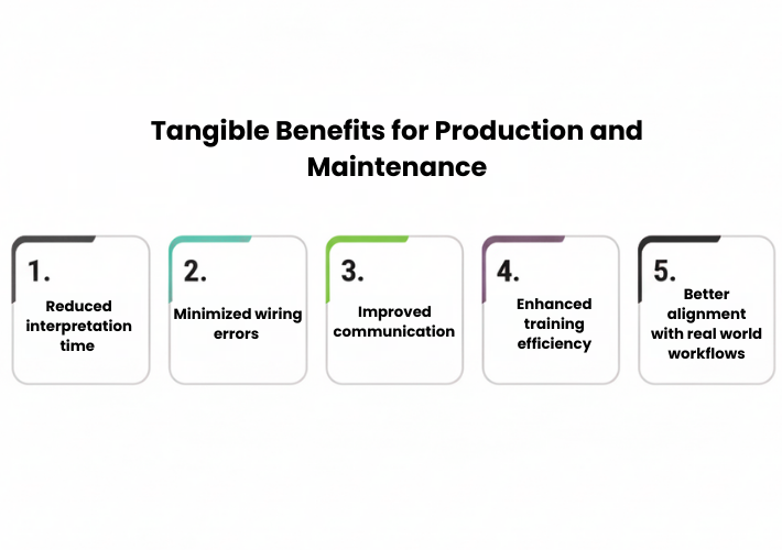
The improved control drawing delivered several significant advantages:
- Reduced interpretation time for technicians on the shop floor, allowing faster assembly and troubleshooting.
- Minimized wiring errors during the production process by providing clearer visual guidance
- Improved communication between engineering and production teams through standardized documentation
- Enhanced training efficiency for new technicians who could more easily understand system operation
- Better alignment with real-world workflows, making the documentation a more valuable resource
This case study demonstrates a crucial aspect of our approach: we understand that technical documentation must serve practical needs, not just meet theoretical requirements. By applying our electrical expertise to improve control drawings, we helped bridge the gap between engineering intent and shop floor implementation.
The client reduced assembly errors by 40% and decreased technician interpretation time by 30%.
Case Study 4: Comprehensive Documentation Package for Ammonia Chiller Systems
Building on our previous case study about enhancing control documentation with ladder logic, we want to showcase another project that demonstrates our comprehensive approach to electrical system design. In this case, we partnered with a manufacturer of packaged ammonia chiller systems to develop a complete electrical design package across multiple system variants with different compressor motor ratings.
For each system variant, we created seven critical documents that together formed a complete electrical design cycle solution. This comprehensive approach ensured consistency of components used, compliance as per UL508a/NEC standards, and manufacturing accuracy across all system variations.
The Seven Essential Design Documents: HVAC-R
1. Load List Analysis
Starting with the client’s provided load list, we carefully detailed the working load requirements of individual components within the chiller system. This foundational document details the power demands of each component, serving as the basis for all subsequent design work and ensuring that Main Disconnect/power distribution would be properly sized for each system variant.
2. Bill of Materials (BOM)
We developed detailed BOMs specific to packaged ammonia chiller systems, including all electrical components such as:
- Circuit breakers, fuses, and other protective devices
- Contactors, relays, and motor starters
- Control transformers and power supplies
- PLCs, HMIs, and other control equipment
- Sensors, transducers, and monitoring devices
- Terminal blocks and connection points
- Enclosures and mounting hardware
Each BOM was tailored to the specific compressor motor rating of that system variant, ensuring accurate component selection and procurement.
3. Short Circuit Current Rating (SCCR) Analysis
Critical for UL 508A compliance, our SCCR Template analyzed whether the system components could withstand potential fault currents. While the client’s system operated with potential fault currents of up to 65kA, our analysis verified component resilience under these conditions providing crucial safety validation and regulatory compliance documentation. This analysis is essential for ensuring that all components in the electrical system can safely handle fault conditions without catastrophic failure.
4. Heat Load Calculations
We prepared detailed heat load calculations that quantified the thermal energy generated by electrical components within the Electrical control panels. This analysis determined the ventilation requirements for each system variant, accounting for factors such as:
- Component power consumption and efficiency
- Ambient temperature conditions
- Enclosure size and ventilation options
- Duty cycles of various components
These calculations are crucial for preventing overheating issues that could lead to premature component failure or system shutdowns.
5. Cable & Wire Schedule
Based on the heat load calculations and system design requirements, we developed comprehensive cable lists detailing crucial specifications including:
- Conductor size (AWG or mm²)
- Insulation type (e.g., THHN, XHHW)
- Voltage and temperature ratings
- Current carrying capacity
- Conduit types and sizes (where applicable)
This document ensured proper wire sizing to handle both operational current and potential fault conditions while maintaining appropriate voltage drop parameters.
6. General Assembly (GA) Drawings
Our GA drawings provided clear visual representations of the control panel layouts for each ammonia chiller system variant. These drawings detailed.
- Overall system dimensions and layout
- Physical arrangement of components within enclosures
- Mounting locations and spacing requirements
- Cable routing paths and access points
- Service clearances and maintenance access
These detailed drawings gave production teams precise guidance for panel assembly and system integration.
7. Wiring Diagrams
We created detailed wiring diagrams showing all electrical connections within the ammonia chiller systems, including:
- Point to point wiring connections between components
- Terminal block assignments and wire numbers
- Control circuit schematics and power distribution paths
- Safety interlocks and protection circuits
- Communication wiring and network connections
These comprehensive diagrams provided a complete roadmap for electricians during panel construction and system installation.
The Value of a Comprehensive Approach -HVAC-R
This complete design package enabled the client to maintain consistency across multiple system variants while ensuring regulatory compliance and manufacturing accuracy. By providing this comprehensive solution, we helped:
- Streamline the client’s production process
- Minimize the chances of errors during assembly and installation
- Ensure compliance with relevant standards and regulations
- Facilitate easier troubleshooting and maintenance
- Support future system modifications and upgrades
The client achieved 100% UL compliance across all system variants while reducing documentation time by 35%.
Additional Electrical Engineering Capabilities – HVAC-R
Beyond our standard documentation packages, Asset-Eyes offers additional specialized electrical engineering services to support HVAC-R manufacturers:
- Loop Drawings: Detailed representations of control loops showing the relationship between field instruments, controllers, and final control elements
- Communication Lists: Documentation of network addresses, protocols, and data points for various controllers in automation systems
- System Architecture Drawings: Visual representations of control system hierarchies, showing relationships between PLCs, HMIs, and field devices
- On-site Panel Engineering Support: Expert assistance during panel assembly, testing, and troubleshooting
- Component Programming: Configuration and programming services for smart devices within control systems
- Control Logic Programming: Development of PLC and controller logic to implement system functionality
- Loop Checking: Systematic verification of control loops to ensure proper operation before system commissioning
The Asset-Eyes Advantage: Design That Excels In The Real World
Our electrical design team brings specialized knowledge that transforms standard drawings into valuable production tools. We don’t simply execute drafting tasks, we actively contribute to making design documentation more effective throughout your production process.
Our electrical drafting specialists understand both the technical requirements of control systems and the practical needs of the technicians who use these drawings. This dual perspective allows us to create documentation that serves as a bridge between engineering design and manufacturing reality.
Whether you’re developing refrigeration systems, industrial ventilation designs, or custom HVAC-R solutions, our team is ready to serve as your dedicated drafting partner delivering documentation that truly supports your business objectives.
Is your team struggling with electrical documentation that doesn’t meet the needs of your production floor?
Schedule a consultation to discover how our approach can transform your workflow and improve manufacturing efficiency.
Key Takeaways: The Value of a True Drafting Partner
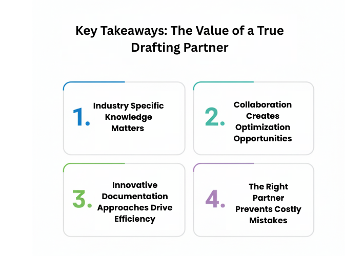
These examples highlight several important benefits of working with a dedicated HVAC-R drafting partner:
1. Industry-Specific Knowledge Matters
Drafting partners with deep HVAC-R experience bring valuable insights that general CAD drafting service cannot provide. Our team understands the practical implications of drafting decisions on manufacturing and system performance.
2. Collaboration Creates Optimization Opportunities
When drafting teams function as an extension of your engineering department rather than simply executing instructions, they can identify opportunities for improvement that might otherwise be missed.
3. Innovative Documentation Approaches Drive Efficiency
Creative approaches to documentation like customizable P&IDs and parametric drawings can transform your workflow and responsiveness to customer needs.
4. The Right Partner Prevents Costly Mistakes
Experienced drafting specialists recognize potential issues before they become problems in production, saving significant time and resources.
Is your engineering team working in silos? Schedule a consultation to discover how our unified approach can transform your workflow.

Conclusion
The most valuable drafting partnerships extend far beyond technical drawing skills. At Asset-Eyes, our solidworks design and general assembly drawing expertise is enhanced by our deep understanding of HVAC-R systems and manufacturing processes. We don’t just create drawings; we contribute meaningful insights that help optimize your products and streamline your workflows.
Whether you’re developing refrigeration systems, industrial ventilation designs, or custom HVAC-R solutions, our team is ready to serve as your dedicated drafting partner delivering documentation that truly supports your business objectives.
Contact us now:
📞 +91 9840895134