Producing a complete electrical panel drawing package typically takes anywhere from two to five business days for a standard, well-templated design, and two to six weeks for a complex, highly customized system. The range is wide because timeline depends far less on raw drafting speed than on how complete and stable the design inputs are, how mature your component library and templates are, and how many review or revision cycles the package goes through before it’s genuinely production-ready. If you’re consistently surprised by how long documentation takes, it’s usually because “ready to start” and “done” mean different things to engineering, project management, and the shop floor.
The Myth of the “Quick Schematic
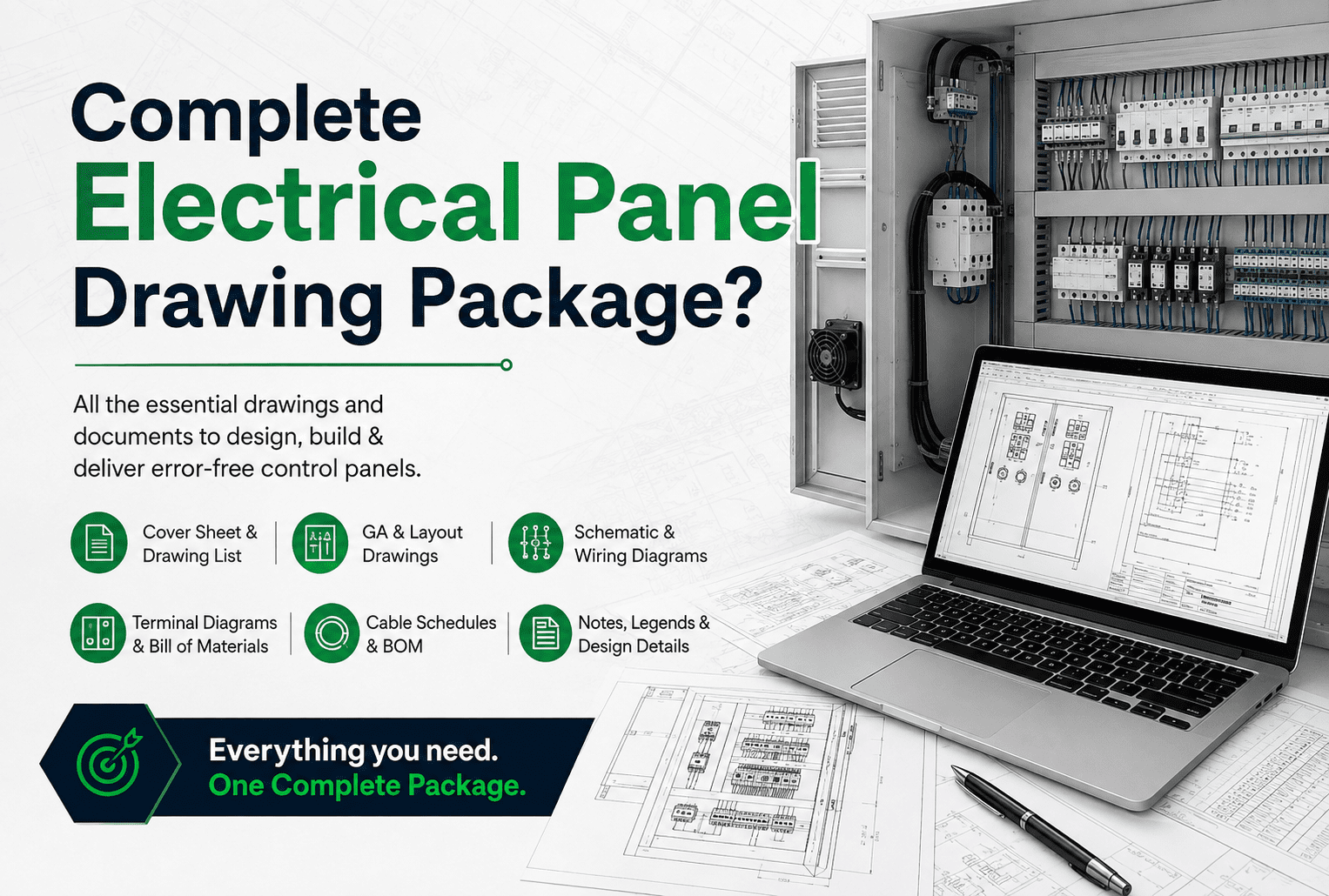
Sales teams and project managers often ask for a “quick schematic” to get the shop floor started, which fundamentally misunderstands what a complete package requires. A schematic is only one piece of the puzzle. A production-ready package needs to include the physical panel layout, a reconciled bill of materials, a terminal plan, wire routing lists, and where applicable SCCR documentation. Rushing the schematic phase alone usually results in components that don’t physically fit the enclosure or a BOM missing long-lead-time items, causing far bigger delays during fabrication than the time it would have taken to do the full package properly the first time. Real speed comes from a systematic, complete process not from rushing the first drawing out the door.
1. Information Gathering and Input Validation
Before CAD work can meaningfully begin, the drafter needs a finalized I/O list, motor list, and environmental requirements. If this information is incomplete, the project enters a holding pattern before it’s even started. This phase often consumes 20% to 30% of total project time, and shortcuts taken here assumptions made to “save time” reliably cause expensive rework later.
2. Base Schematic and Component Selection
This phase covers selecting the correct breakers, contactors, PLCs, and power supplies, and routing the control logic across schematic pages. For a standard panel drawn from pre-built macros in a mature component library, this can take a few days. For a custom panel requiring new component research or a novel control architecture, this phase alone can consume a week or more.
3. Physical Layout and Spacing
Once the schematic is drawn, components have to be arranged in the physical enclosure. This is where spacing requirements, wire duct sizing, and thermal management get validated. If selected components don’t fit, the drafter has to return to phase two and select alternatives. This phase typically takes one to three days depending on enclosure constraints.
4.Automated Reporting and Package Generation
Generating the BOM, wire lists, and terminal plans should be the fastest part of the process. In an intelligent electrical CAD environment, this takes hours. Done manually counting components and cross-referencing spreadsheets this phase can add days and introduces a real risk of human error.
As a rough planning model, total timeline can be thought of as:
Total Time = Input Time + (Number of Sheets × Drafting Time per Sheet) + Layout Time + Review Time
where:
- Input Time= time spent gathering and validating requirements
- Number of Sheets= number of schematic pages
- Drafting Time per Sheet= average drafting time per sheet (which drops significantly with a mature macro library)
- Layout Time= physical layout and spacing validation
- Review Time= internal QA and revision time
Reducing the total timeline means shrinking each of these terms individually enforcing input cutoffs, using validated macros to reduce Drafting Time per Sheet, and structuring the review process so it doesn’t require a full re-check of the entire package.
Realistic Timeline Benchmarks by Panel Type
These benchmarks assume complete, stable design inputs and a reasonably mature component library, and represent elapsed calendar time not just raw drafting hours.
Simple motor control or distribution panel (10–15 schematic sheets, standard architecture, established template): 16–24 engineering hours, roughly two to four business days.
Mid-complexity machine control panel (20–35 sheets, mixed I/O, standard power distribution, single safety relay): 32–60 engineering hours, roughly five to eight business days.
Complex multi-function control panel (40–60 sheets, distributed I/O, multiple voltage levels, safety architecture): 60–100+ engineering hours, roughly ten to fifteen business days.
Large multi-section MCC or integrated control system (60+ sheets, multiple enclosures, complex power architecture): 100+ engineering hours, typically three to six weeks, with timeline heavily dependent on customer review cycles.
If your actual timelines fall well outside these ranges, the issue is very likely one of the four phases above most often incomplete inputs or an immature component library not how fast your drafters can physically work.
Why Internal Estimates Are Often Wrong
Three estimation traps show up repeatedly:
Confusing net drawing time with real calendar time: Someone remembers “I drew that in two days” but forgets the week lost waiting on I/O finalization and the week spent on customer review comments.
Ignoring rework cycles: Every late design change a different VFD size, a relocated terminal block, an adjusted safety circuit typically affects multiple pages, not just one, and each of those pages has to be redrafted and re-reviewed.
Underestimating non-schematic deliverables: Terminal plans, wire lists, and as-built updates are rarely accounted for explicitly in early estimates, even though they can represent a third or more of total engineering hours on a complex package.
A more accurate internal benchmark asks: “How long did it actually take, start to finish, including all the waiting and rework, the last time we built a similar panel?” — not how long the drafting itself took in isolation.
What Compresses vs. Extends the Timeline
Compresses it: A structured handoff format with a complete, organized specification; a mature, validated component library that lets drafters select rather than manually enter component data; a defined design-freeze gate before drafting starts; and parallel review of completed sections rather than a single review pass at the end.
Extends it: Incomplete or changing design inputs after drafting has started; generic CAD environments requiring manual BOM reconciliation; slow or multi-round review processes; and single-drafter dependencies that force context-switching across multiple concurrent projects.
How Asset-Eyes Delivers Predictable Drawing Package Timelines
Asset-Eyes scopes drawing packages based on complexity, input completeness, and standards maturity before drafting starts not after. We define what “complete package” means for your shop and your customers, lock input requirements (I/O list, load list, applicable standards) before work begins, use modern electrical CAD tools and reusable macros wherever possible, and build in structured review points instead of a single end-of-project check. The result is a documentation timeline your project manager can actually plan a fabrication schedule around, not a best-case estimate that quietly slips.