
Introduction
Picture a commissioning floor a few weeks before a machine is scheduled to go live. The mechanical build is complete, the controls engineer is deep into servo tuning and PLC logic, and the cycle time still isn’t hitting target. The instinctive move is to ask the controls team to “optimize it” tighten a motion profile, shave a dwell timer, sequence a handoff more cleverly. It’s a reasonable instinct. It’s also usually the wrong place to look.
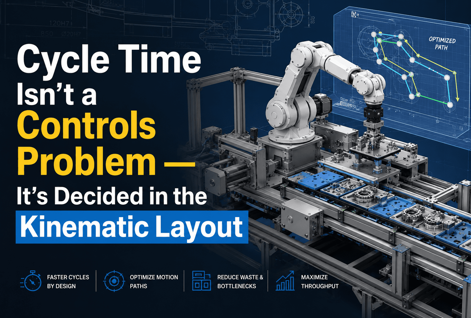
By the time a controls engineer is tuning cycle time, the machine’s kinematic architecture has already set the ceiling on what’s achievable. The stroke lengths, the transfer concept, the number of stations, the way motions are sequenced relative to one another all of that was decided months earlier, at the layout stage, long before a single line of PLC code existed. Controls can optimize brilliantly within that ceiling. It cannot raise it.
This is the same principle behind a “kinematics first” approach to special purpose machine design: cycle time isn’t a controls problem to be solved at the end of a project it’s a mechanical design decision that has to be made deliberately at the beginning. This article walks through why that’s true, which specific kinematic decisions actually set the throughput ceiling, and what it looks like to design cycle time in rather than chase it later.
Why Controls Gets Blamed First
It’s easy to see why cycle time conversations default to the controls side of the machine. A servo’s motion profile is visible on a screen. Acceleration ramps, dwell timers, and handoff sequences can be adjusted in software, often in real time, with an immediate and satisfying feedback loop.
Mechanical geometry doesn’t work that way. It was decided months earlier and is now embedded in steel, aluminum, and fixed linkage geometry. It has no tuning parameter, and because it feels “finished” by the time commissioning starts, it rarely comes back under scrutiny even when it’s the actual constraint everyone is fighting.
The result is a quiet misattribution: controls engineers inherit a mechanical architecture and then get evaluated on whether the machine hits a cycle time target that architecture may never have been capable of reaching in the first place.
The Kinematic Layout Is Your Throughput Budget
It helps to think of the kinematic layout as a budget. Every motion in the machine — every index, every transfer, every stroke — costs time. The layout decides how many of those motions exist, how long each one takes at its physical minimum, and which ones can happen simultaneously versus which ones must happen one after another.
Total cycle time is essentially the sum of every motion segment that cannot be run in parallel, plus the dwell time required for the process to complete at each station. That sum is set almost entirely by mechanical decisions — the transfer mechanism chosen, the stroke lengths involved, the mass being moved, and how stations are arranged relative to one another.
A controls engineer can spend that budget wisely. They can eliminate wasted delays and sequence operations as efficiently as the mechanism allows. What they cannot do is create time that the layout never budgeted for in the first place.
The Design Decisions That Set the Ceiling
Transfer Architecture: Serial vs. Parallel Stations
The single most consequential kinematic decision is usually how parts move through the machine. A rotary index table, a linear walking-beam transfer, a servo gantry, and a conveyor-based system each carry fundamentally different timing characteristics — not just in raw speed, but in whether the machine can work on multiple parts at once.
In a serial arrangement, one part moves through every operation in sequence, and total cycle time is close to the sum of every operation’s duration. In a parallel arrangement, several stations work simultaneously on different parts, and cycle time is closer to the duration of the single slowest station — the bottleneck — rather than the sum of everything. Whether a machine is fundamentally serial or parallel is locked in the moment the layout chooses a single-station concept over a multi-station index table. No amount of code changes that after the fact.
Cam-Linkage Mechanisms and Dwell-to-Motion Ratios
For machines using cam-driven mechanisms — still common in high-speed applications for their repeatability and lack of backlash the cam profile physically encodes the ratio between dwell time and motion time. That ratio is fixed the moment the cam geometry is cut.
If a downstream process needs more dwell time than the original cam profile allows, there’s no software patch for it — the cam has to be redesigned and remade. This is exactly why dwell requirements need to be agreed upon between process and mechanical teams during the kinematic design phase, not discovered afterward on the floor.
Stroke Length and Kinematic Efficiency
Every linear motion has a stroke length dictated by the geometry of the task, and every one of those strokes fights inertia. The relationships are basic physics:
F = m × a (Force = mass × acceleration)
T = I × α (Torque = moment of inertia × angular acceleration)
A heavier moving mass or a mechanism with greater rotational inertia simply requires more force or torque — or more time — to accelerate and decelerate safely. If a linkage’s geometry demands more travel than the actual part movement strictly requires, that inefficiency is paid for on every single cycle, for the life of the machine. Minimizing that gap through careful kinematic synthesis is a design-stage lever, and it stops being available the moment steel is cut.
Motion Overlap Potential
One of the most powerful ways to reduce cycle time is running multiple motions simultaneously rather than sequentially. Whether that’s possible is almost entirely a mechanical question — it depends on whether two motions share a structural load path, interfere with each other physically, or compete for the same actuator.
A layout designed with motion independence in mind from the start can achieve meaningful cycle time reduction through overlap without increasing any individual motion’s speed. A layout that ignores this dynamic coupling forces the controls engineer to sequence motions defensively later on, adding time that was never part of the plan.
Ergonomics and Safety Constraints
Finally, some limits on speed exist for good reason and can’t be tuned away. Guard openings, approach speeds near operator loading zones, and manual-assist steps all impose hard limits that have to be accounted for in the layout — reach zones, visibility, and maintenance clearances included. A machine that crowds people into tight spaces next to fast-moving mechanisms will always be slowed down for safety, regardless of how well the controls are tuned.
Validated Motion Analysis: Engineering the Answer, Not Guessing
Designing a kinematic layout without motion analysis is a bit like laying out a road without knowing the speed limit — you might get lucky, but you’re guessing rather than engineering. Validated motion analysis performed at the layout stage, before detailed design is locked, is what answers the questions that actually determine whether a cycle time target is realistic:
- What is the theoretical minimum cycle time given the required motions and their physical constraints?
- Which motion segment represents the critical path that limits the entire cycle?
- Where can overlap be introduced, and what structural or geometric conditions need to be true for it to work safely?
- Do the resulting velocity, acceleration, and force profiles stay within the operating limits of the drive systems being considered?
Doing this analysis early keeps every one of these questions open to design change. Doing it late — or not at all — turns it into a forensic exercise explaining why the machine can’t hit its number.
Drive Sizing and Structural Stiffness Are Downstream Consequences
Servo, ball screw, and pneumatic sizing often get treated as controls-adjacent decisions, but they’re really mechanical consequences of the kinematic layout. The torque and speed required from a drive are set by the inertia of the moving mass, the required acceleration, and the stroke length — all of which come from the layout itself, not from the drive selection process. If a drive is undersized relative to what the kinematics demand, a controls engineer can’t compensate; they can only reduce the achievable speed, which increases cycle time, or flag an engineering change.
Structural stiffness matters for a similar reason. A frame that deflects or vibrates under dynamic load introduces settling time before a station can reliably begin its process. That settling time is locked in by member cross-sections, connection geometry, and mass distribution — decisions made during structural design. A stiffer, better-designed frame settles faster and enables tighter motion overlap, which is a throughput benefit that originates entirely upstream of controls.
The Commissioning Asymmetry
When a cycle time shortfall surfaces at commissioning, the available fixes are almost never simple. Modifying a cam profile, changing a transfer stroke, adding a station, or stiffening a frame all require fabrication, disassembly, and requalification — expensive and slow by nature. Controls optimization, by comparison, is fast and low-cost, but it can only recover time that the mechanical architecture actually left available. If the kinematic layout was never analyzed against the cycle time target, there may be very little left to recover.
This asymmetry is the practical argument for treating kinematic design rigorously at the front of a project: a thorough motion study during layout is a small fraction of the cost of a mechanical change order after the machine has already been fabricated.
How Asset-Eyes Approaches Kinematic Design
As a machine design and engineering services company working across manufacturing industries, we treat cycle time as a design input from day one, not something to be recovered during commissioning. That starts with collaborative requirement specification: understanding process requirements, throughput targets, operating conditions, and how a new machine needs to integrate with the equipment already on the floor.
From there, our engineering design services move into kinematic design and motion system engineering cam-linkage mechanisms, linear guides, rotary index tables, and custom transfer systems validated with motion analysis before detailed design is finalized. Drive system sizing for servo, ball screw, rack-and-pinion, pneumatic, and hydraulic systems, along with structural framework design covering bending, shear, and deflection, follows directly from that kinematic groundwork rather than being handled as a separate step. Tooling interfaces, controls loading stations, and ergonomic work envelopes are engineered alongside the motion system so speed and safety are never fighting each other later.
Every one of these decisions is captured in a complete engineering documentation package — 3D assembly models, GD&T-compliant fabrication drawings, a clear general assembly drawing, bills of materials, and assembly instructions built through solidworks design and disciplined cad drafting services so that fabricators and integrators can execute the design exactly as engineered. We also provide engineering support through commissioning, helping interpret and refine design decisions if real-world conditions require it but the hands-on build and installation of the machine sits with your team or integrator, not with us.
The causal chain matters here: cycle time, field modification counts, and time-to-release are all set by the kinematic and structural choices made long before a machine reaches the floor. Getting those decisions right at the design stage is what makes a smooth, fast commissioning possible in the first place.
Key Takeaways
Cycle time isn’t decided at the PLC it’s decided at the layout stage, when someone chooses stroke lengths, transfer architecture, cam profiles, and station arrangement. Controls can optimize brilliantly within the ceiling that layout creates, but it can’t raise that ceiling after the fact. Validated motion analysis, deliberate drive sizing, and structural stiffness planning, done during kinematic design rather than after fabrication, are what turn a cycle time target from a hopeful number into an engineered outcome.
If your commissioning process keeps turning into a scramble to recover seconds through code changes, that’s usually a sign the cycle time work needed to happen earlier — in the kinematic layout, not the control cabinet.
Discuss Your Engineering Requirements
Schedule a discovery call with us today: [Calendly — Welcome to Asset-Eyes Infomatics]
📞 +91 9840895134
FAQs
Why isn’t cycle time primarily a controls problem in special purpose machines?
Cycle time isn’t primarily a controls problem because the kinematic layout sets the ceiling on what’s achievable long before a controls engineer starts tuning. Stroke lengths, transfer architecture, cam profiles, and station arrangement are mechanical decisions made months earlier and already embedded in steel by the time commissioning begins. Controls can optimize within that ceiling, but they cannot raise it after the fact.
What is a kinematic layout, and why does it function as a machine’s throughput budget?
A kinematic layout is the mechanical architecture of a machine its transfer mechanism, stroke lengths, station arrangement, and motion sequencing. It works like a throughput budget because every motion costs time, and the layout decides how many motions exist, how long each takes at minimum, and which can run in parallel versus sequentially. Controls can spend that budget efficiently but cannot expand it.
How does transfer architecture — serial versus parallel stations — affect machine cycle time?
Transfer architecture is the single most consequential kinematic decision for cycle time. In a serial arrangement, one part moves through every operation, so cycle time is close to the sum of all operation durations. In a parallel arrangement, such as a rotary index table, multiple stations work simultaneously, making cycle time closer to the duration of the slowest bottleneck station rather than the total sum of every step.
Why can’t controls engineers adjust dwell time on cam-driven mechanisms?
Controls engineers can’t adjust dwell time on cam-driven mechanisms because the ratio between dwell time and motion time is physically encoded into the cam’s geometry the moment it’s cut. If a downstream process needs more dwell time than the profile allows, there’s no software fix the cam has to be redesigned and remade, which is why dwell requirements must be settled during kinematic design, not discovered later.
Why does stroke length matter for a machine’s cycle time?
Stroke length matters because every linear motion fights inertia, and a heavier moving mass or greater rotational inertia requires more force or more time to accelerate and decelerate safely. If a linkage’s geometry demands more travel than the actual part movement requires, that inefficiency is paid for on every cycle for the machine’s life a gap that can only be minimized before steel is cut.
How does motion overlap reduce cycle time without increasing motion speed?
Motion overlap reduces cycle time by letting multiple motions run simultaneously instead of sequentially, without speeding up any individual motion. Whether overlap is possible depends almost entirely on mechanical factors whether two motions share a structural load path, physically interfere, or compete for the same actuator. A layout designed for motion independence from the start enables this; otherwise, controls must sequence motions defensively, adding time.
Why is validated motion analysis critical during the kinematic layout stage?
Validated motion analysis is critical because it answers, before detailed design is locked, whether a cycle time target is realistic identifying the theoretical minimum cycle time, the critical-path motion segment, where overlap can be introduced, and whether resulting force profiles stay within drive limits. Performing this analysis early keeps design changes open; performing it late turns it into a forensic exercise explaining a missed target.
How do drive sizing and structural stiffness affect cycle time as consequences of the kinematic layout?
Drive sizing and structural stiffness are mechanical consequences of the kinematic layout rather than controls-adjacent decisions. Required torque and speed are set by the inertia, acceleration, and stroke length the layout demands, so an undersized drive can only force slower motion. Likewise, a frame that deflects or vibrates introduces settling time before a station can begin its process, while a stiffer frame settles faster and enables tighter motion overlap.
Why is fixing cycle time issues during commissioning more expensive than addressing them at the layout stage?
Fixing cycle time issues during commissioning is expensive because mechanical changes modifying a cam profile, changing a transfer stroke, adding a station, or stiffening a frame — require fabrication, disassembly, and requalification. Controls optimization is fast and low-cost by comparison, but it can only recover time the mechanical architecture actually left available. A thorough motion study at the layout stage costs a fraction of a later change order.
How does Asset-Eyes approach cycle time and engineering documentation in special purpose machine design?
Asset-Eyes treats cycle time as a design input from day one rather than something to recover at commissioning. Work begins with collaborative requirement specification around throughput targets, then moves into kinematic design, validated motion analysis, drive sizing, and structural framework design, with every decision captured in a complete engineering documentation package 3D assemblies, GD&T-compliant drawings, general assembly drawings, and BOMs while hands-on build and installation remain with the client’s team or integrator.