Picture this: You’re reviewing a pressure vessel design that’s nearly complete. The engineers have completed the shell calculations, locked in the head geometry, and finalized the support structure. Then the team asks about nozzle placement, a small detail that is often treated casually. Too often, someone responds, “Just put them wherever they fit around existing features.” This ignores how their position affects efficiency, safety, and maintenance. Thoughtful nozzle placement can significantly improve overall system performance.
When engineers treat nozzle placement as a space-filling task after completing the main design. It creates flow problems and stress concentrations. And maintenance issues that persist for decades.
The reality is that every nozzle position you choose shapes how your vessel performs thermally, structurally, and operationally. These connection points aren’t just holes in a shell; they’re the interfaces where your vessel interacts with the entire process system. When nozzle placement decisions are made thoughtfully and early, engineers therefore produce equipment that functions as intended. Conversely, if they treat these decisions as mere details, the team inevitably encounters expensive surprises.
This article explores why nozzle placement deserves first-class engineering attention. It highlights the problems that occur when engineers neglect it and shows how proper CAD design services help teams make these critical decisions before cutting any steel.
1. Why Nozzle Placement Gets Pushed to the End
Understanding how this problem develops helps explain why it’s so persistent. In most vessel design workflows, the major structural decisions come first: shell diameter and thickness, head selection, pressure calculations, and support design. These feel like the “big” engineering decisions because they directly relate to code compliance and structural integrity.
Teams typically decide nozzle placement after positioning everything else, constrained by the remaining space. By this point, they focus on completing drawings and meeting deadlines. The default approach often becomes: “We’ll position the nozzles to clear the supports and satisfy the piping requirements.”
The problem with this sequence is that nozzles aren’t just connection points; they’re process-control elements, structural discontinuities, and maintenance access points all rolled into one. Treating their placement as secondary guarantees you’ll have to combat their compromised performance during operation rather than preventing them in design.
2. The Four Critical Impact Areas of Nozzle Placement
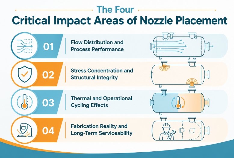
2.1 Flow Distribution and Process Performance
Think of a pressure vessel like a room where you’re trying to achieve even temperature distribution. Where you place the heating inlet and the air return determines whether you get uniform conditions or hot and cold spots. The same principle governs fluid vessels.
When engineers position inlet nozzles without considering internal flow paths, nozzle placement creates preferential flow patterns. Fluid follows the path of least resistance. often short-circuits directly from the inlet to the outlet and bypassing large portions of the vessel volume. In heat exchangers, this produces thermal gradients, leaving some zones hot while others stay cool. In separation vessels, it disrupts the residence time that the entire separation process depends on.
Outlet positioning compounds these issues. An outlet placed too close to an inlet encourages short-circuiting, where fluid exits before completing its intended process cycle. In reactors and mixing vessels, this can mean incomplete reactions or poor product quality. The solution isn’t just separation distance; it’s deliberate positioning that encourages the flow path your process actually requires.
2.2 Stress Concentration and Structural Integrity
From a structural perspective, every nozzle opening is a discontinuity that interrupts the shell’s natural stress distribution. Under internal pressure, the shell wants to expand uniformly. A nozzle creates a geometric interruption that concentrates stress at the junction between the nozzle neck and shell wall.
Engineers manage individual nozzles using proper reinforcement pads and weld design, following ASME Section VIII or EN 13445. Additionally, nozzle placement determines how stress concentrations interact with each other and with other structural features. For example, placing two large nozzles too close causes their stress fields to overlap, creating combined stress levels higher than either would produce alone. Moreover, positioning a nozzle near a head-to-shell seam or support attachment introduces stress into an area already handling complex load paths.
These interactions aren’t always obvious without proper analysis, but they’re far easier to address during design than after fabrication. This is where solid modeling and competent machine design company expertise become invaluable. You can visualize and analyze these interactions before they become expensive problems.
2.3 Thermal and Operational Cycling Effects
Pressure vessels rarely operate under constant conditions. They heat up, cool down, cycle between different operating pressures, and handle varying product compositions. Nozzle placement can either mitigate or amplify the stresses these cycles create.
Consider an inlet nozzle that introduces a fluid that’s significantly hotter or colder than the bulk vessel temperature. This creates localized thermal gradients around the nozzle area. If that region is near a structural discontinuity like a support attachment or major weld seam, you’ve created a fatigue-prone zone that will accumulate damage over thousands of thermal cycles.
Vertical vessels present additional challenges as they expand and contract with temperature changes. A nozzle rigidly connected to fixed piping at the top of a tall vessel can experience substantial movement as the shell grows with heat. First, poor nozzle elevation and inadequate piping flexibility can over-stress both the nozzle and connected lines.
2.4 Fabrication Reality and Long-Term Serviceability
The best nozzle placement on paper means nothing if fabricators cannot build it properly or maintain it safely. Welders need physical access to complete full-penetration welds around nozzle necks. Positioning nozzles too close to structural attachments, other nozzles, or vessel geometry constraints creates welding access problems that compromise joint quality.
A vessel might operate for twenty to thirty years, during which teams will inspect, clean, repair, and modify it multiple times. Every maintenance activity is influenced by nozzle placement and accessibility.
Carefully consider the following concerns as they determine whether routine maintenance takes hours or days:
Can technicians reach the flange bolts with standard tools? Has the nozzle placement ensured the drain nozzle sits at the true low point, or will operators struggle with residual fluid every time they empty the vessel? Are instrument connections positioned to provide accurate readings of actual vessel conditions?
3. The Power of Early-Stage Nozzle Placement Analysis
Getting nozzle placement right requires treating it as a first-class design activity from day one. Engineers must work through placement logic before finalizing shell geometry and support structures, while design freedom still allows for optimization.
Effective early-stage analysis addresses several key areas simultaneously. Process requirements drive the fundamental question: what flow path should fluid follow inside the vessel? This determines inlet orientation, internal baffle positioning, and outlet location to maximize residence time and process efficiency.
Structural considerations define minimum spacing for nozzle placement, preventing stress field overlap, maintaining safe distances from major weld seams, and ensuring clearances from support attachments. Engineers also plan maintenance accessibility so that each connection point can be easily accessed, bolted, and unbolted once installed.
Finally, piping system coordination determines the elevations and orientations required by the surrounding plant layout, minimizing pipe stress and routing complexity that would otherwise feed back into the vessel structure.
4. How Modern CAD Design Services Change the Game
The shift to 3D modeling has fundamentally changed how nozzle placement decisions can be made and validated. In a well-structured SolidWorks design environment, you can anticipate the internal flow paths implied by your nozzle positions based on geometry and layout even before running detailed simulations. You can also check clearances between nozzle projections and internal components and simulate maintenance access scenarios before fabrication begins.
This is where professional CAD drafting services deliver genuine value beyond just producing drawings. A well-executed 3D model becomes an analysis environment where placement decisions can be tested against real constraints. You can virtually place wrenches on flanges to verify clearances, model the approach paths for internal component removal, and coordinate with piping designers using accurate reference geometry.
The general assembly drawing produced through this process captures all this critical design intelligence. When nozzle placement. When engineers fully define nozzle placement in the GA drawing, including positions, orientations, and projections, fabricators gain clarity, inspectors receive clear reference dimensions, and installation teams confidently plan their tasks.
5. Standards and Code Considerations
Nozzle placement isn’t purely a judgment call; established codes and standards provide minimum requirements that constrain certain placement decisions. ASME Section VIII Division 1 and EN 13445 specify reinforcement requirements and define reinforcement zone limits, which directly determine nozzle placement relative to each other and to structural discontinuities.
Industry standards like TEMA for shell-and-tube heat exchangers provide specific guidance on inlet and outlet nozzle positioning relative to tube bundles, guidance developed to prevent the flow distribution problems that compromise thermal performance. These standards encode hard-won knowledge about failure modes that result from poor placement decisions.
Understanding these requirements isn’t just about compliance; It’s about recognizing that the engineering community has already documented many problems that arise when nozzle placement decisions are made carelessly.
6. How Asset-Eyes Approaches Nozzle Placement as System Design
As a machine design company, Asset-Eyes treats pressure vessels and boilers as integrated systems where nozzle placement is a fundamental design decision, not a drafting afterthought. Our approach integrates placement analysis into the design process from the beginning.
We use comprehensive CAD drawing services to model nozzle layouts alongside internals, supports, and external piping connections from day one. This allows us to identify and resolve conflicts between process requirements, structural constraints, and maintenance accessibility before they become fabrication problems.
Our CAD drafting services convert these carefully considered placement decisions into precise fabrication documentation. We produce detailed nozzle schedules, orientation drawings, and general assembly drawing that clearly communicate design intent to fabricators, inspectors, and maintenance teams.
Because we work across heavy industrial equipment, vessels & boilers, and broader machine design applications, we bring a systems perspective to every project. Nozzle placement isn’t just a vessel design concern; it’s part of how the entire system integrates and performs over its operational life.

Conclusion
Nozzle placement directly shapes every aspect of vessel performance: it determines how fluid flows through the system, where stresses concentrate, how thermal cycles affect long-term durability, and whether technicians can maintain the equipment efficiently over decades of service.
When engineers make nozzle placement decisions deliberately and early in the design process, using proper 3D modeling and analysis, vessels perform as intended, age gracefully, and support efficient operations. When teams treat nozzle placement as a minor detail to resolve later. The equipment challenges operators throughout its entire service life.
The connection points you position today define how your vessel will behave for the next twenty years. Making those decisions with the care and analysis they deserve is one of the most straightforward ways to ensure your equipment delivers the performance and reliability your process demands.
Contact Us Now:
📞 +91 9840895134
Frequently Asked Questions
Nozzle placement often gets pushed to the end because teams first focus on major structural decisions, such as shell sizing, head design, and pressure calculations. Consequently, by the time nozzles are considered, remaining space and tight deadlines drive a “wherever they fit” approach. However, this sequence ignores the fact that nozzles are not only process control elements but also structural discontinuities and maintenance access points, all of which significantly shape vessel performance for decades. Therefore, treating placement as secondary inevitably guarantees compromised operational performance.
Poor nozzle placement creates preferential flow patterns where fluid short-circuits directly from inlet to outlet, bypassing large portions of vessel volume. In heat exchangers, this causes thermal gradients with hot and cold zones. In separation vessels, it disrupts the residence time that separation processes depend on. In reactors and mixing vessels, inadequate placement leads to incomplete reactions or poor product quality because fluid exits before completing intended process cycles.
Every nozzle opening creates stress concentrations that interrupt the shell’s natural stress distribution under pressure. When two large nozzles are placed too close together, their stress fields overlap, creating combined stress levels higher than either would produce alone. Positioning nozzles near head-to-shell seams or support attachments introduces additional stress into areas already managing complex load paths. These interactions are far easier to address during design than after fabrication.
Thermal and pressure cycling amplify stresses around poorly placed nozzles over thousands of operating cycles. Inlets introducing significantly hotter or colder fluids create localized thermal gradients, especially problematic near weld seams or support attachments where fatigue damage accumulates. In tall vertical vessels, thermal expansion causes shell movement; rigidly connected nozzles with inflexible piping experience substantial stress as vessels grow with heat, potentially damaging both nozzles and connected lines.
The nozzle placement has determined fabrication feasibility and maintenance efficiency for decades. During fabrication, welders need physical access for full-penetration welds around nozzle necks; cramped arrangements near supports or other nozzles compromise joint quality. Over a vessel’s twenty to thirty-year service life, poor placement makes routine maintenance take days instead of hours. Technicians may be unable to reach flange bolts, drain nozzles positioned away from true low points leave residual fluid, and instrument connections provide unrepresentative readings.
The nozzle placement analysis should begin before shell geometry and support structures are finalized, when design freedom still exists to optimize decisions. Early-stage analysis simultaneously addresses process requirements, determining desired internal flow paths, structural considerations, establishing minimum spacing to prevent stress field overlap, maintenance accessibility planning, ensuring practical tool access, and piping system coordination, minimizing pipe stress. This integrated approach prevents the compromises that result from treating placement as space-filling after major decisions are locked.
ASME Section VIII Division 1 and EN 13445 establish minimum requirements by specifying reinforcement requirements and defining reinforcement zone limits, directly affecting how close nozzles can be positioned to each other and structural discontinuities. Industry standards like TEMA for shell-and-tube heat exchangers provide specific guidance on inlet and outlet positioning relative to tube bundles to prevent flow distribution problems. These standards encode hard-won knowledge about failure modes resulting from careless placement decisions.
Modern SolidWorks design environments transform nozzle placement from guesswork into validated engineering decisions. Engineers can anticipate internal flow paths implied by nozzle positions, check clearances between nozzle projections and internal components, and simulate maintenance access scenarios before fabrication begins. Teams can virtually place wrenches on flanges to verify clearances, model internal component removal paths, and coordinate with piping designers using accurate reference geometry, catching expensive conflicts while they remain digital problems.
Comprehensive nozzle placement documentation should include detailed nozzle schedules, orientation drawings, and general assembly drawings that clearly communicate design intent. When nozzle positions, orientations, and projections are fully defined in GA drawings, fabricators work with clarity rather than assumptions, inspectors have unambiguous reference dimensions, and installation teams can plan confidently. This documentation should carry forward all design intelligence developed during 3D modeling and placement analysis, ensuring decades of operational clarity.
Asset-Eyes treats nozzle placement as a fundamental system design decision integrated from project inception rather than a drafting afterthought. Using comprehensive CAD design services, they model nozzle layouts alongside internals, supports, and external piping connections from day one, identifying and resolving conflicts between process requirements, structural constraints, and maintenance accessibility before fabrication begins. Working across heavy industrial equipment, vessels, and boilers, and machine design applications, they ensure nozzle placement decisions support optimal performance throughout the equipment’s operational life.