Picture this: You’re staring at a perfectly finalized electrical control panel design. Every wire is routed, every clearance is checked, and the EPLAN electrical drawings are ready for fabrication. Then, suddenly, the reality of Engineering Jenga hits. The variable frequency drive you specified faces a 40-week lead time, or worse, the manufacturer declares it obsolete.
You need to swap it out for an alternative. How hard could it be when it’s just one component, right?
Welcome to Engineering Jenga. Just like removing a wooden block from a carefully balanced tower, swapping a single component in a complex industrial system can send shockwaves through your entire project. In some cases, the system adapts smoothly. However, in other situations, unexpected engineering conflicts can cause the entire design to collapse. As a result, even a minor component substitution can create delays, redesign work, and production risks. Ultimately, the difference depends on how well the original design was engineered to handle change.
Let’s explore the ripple effects of component obsolescence and supply chain substitutions, why some designs absorb change gracefully while others collapse under it, and what separates robust engineering from fragile systems that can’t survive the real world.
1. The Engineering Jenga Substitution Illusion: Why “Same Function” Doesn’t Mean “Same Impact.”
When a component needs replacement, the instinct is to find the nearest functional equivalent. Same voltage rating, similar performance specs, comparable price point. The procurement team finds a substitute. The engineer signs off on the specifications. And everyone assumes the problem is solved.
This is what we call the “substitution illusion,” the assumption that functionally equivalent components will have an equivalent impact on your design. In reality, components don’t exist in isolation. They exist in relationship to everything around them.
Consider a motor control panel design where a specific contactor becomes unavailable. Although the replacement may have identical electrical ratings, it might use a slightly different footprint. As a result, that small dimensional change affects DIN rail spacing. Then, the spacing change impacts the enclosure layout, cable management, and door clearance. In some cases, it could even invalidate the entire panel’s UL listing.
You pulled one block, and suddenly half the tower is wobbling.
The challenge with complex systems, whether it’s HVAC equipment design, SolidWorks design assemblies, or comprehensive machine design company projects, is that “same function” rarely translates to “same fit.” As a result, even small component substitutions can disrupt the spatial, thermal, and interface relationships that define modern industrial equipment.
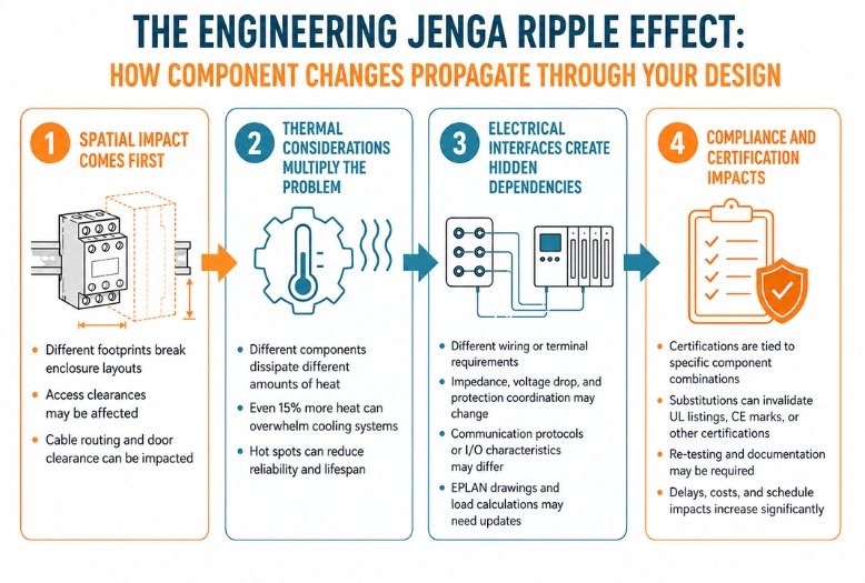
2. The Engineering Jenga Ripple Effect: How Component Changes Propagate Through Your Design
Single-component changes can be so disruptive because the impact spreads through different dimensions of your design.
Spatial Impact Comes First
Physical dimensional differences usually create the first problem. Even small changes, such as a component becoming 10mm taller or 15mm deeper, can cause cascading layout issues in tightly optimized designs. As a result, your general assembly drawing that once showed perfect clearances may now reveal conflicts. In addition, carefully planned cable routing may interfere with the larger component body. Service access can also become difficult when access panels no longer provide enough clearance.
This is where quality CAD drawing services and parametric SolidWorks drafting services prove their value. If your 3D models are properly constrained and intelligent. You can quickly visualize whether a substitute component fits or what needs to change to make it fit.
Thermal Considerations Multiply the Problem
Different components generate different heat loads, even when they’re functionally equivalent. A replacement drive that dissipates just 15% more heat can push a carefully calculated thermal management system past its limits. In compact industrial ventilation systems, design or enclosed control panels. Thermal calculations are often done to tight margins.
When thermal loads change, you might need to:
- Resize cooling fans or add supplemental ventilation
- Increase spacing between heat-generating components
- Upgrade enclosure ratings or add heat exchangers
- Recalculate derating factors for adjacent temperature-sensitive devices
Electrical Interfaces Create Hidden Dependencies
Voltage drops, impedance characteristics, and communication protocols often vary between manufacturers, even when components appear “equivalent.” As a result, your EPLAN control panel design files may require updates to accommodate different wiring requirements, protection coordination, or load calculations.
In automated systems, even simple component substitutions can disrupt communication networks, require firmware updates, or force engineers to modify the entire control architecture. This usually happens when the replacement component uses different communication protocols or supports different I/O characteristics.
Compliance and Certification Impacts
Perhaps the most overlooked consequence involves certifications and safety compliance. In many cases, certifications and safety ratings depend on specific component combinations. As a result, substituting a part, even with a technically superior alternative, can invalidate existing UL listings, CE marks, or industry-specific certifications. Consequently, manufacturers may need to perform expensive and time-consuming re-testing before production can continue.
3. Warning Signs of Engineering Jenga in a Fragile Design
Some designs are structurally fragile from the start. Watch for these red flags:
- Tightly coupled systems with no modularity, where every component’s specifications derive directly from adjacent components
- Single-source dependencies make you vulnerable to any supplier disruption
- Outdated documentation where your drawings no longer match what’s actually installed on the factory floor
- Undocumented design intent where engineers didn’t capture why specific components were chosen. Leaving future engineers to guess at critical constraints
- Designs built to exact minimums with no thermal, spatial, or electrical margins. These designs work perfectly under ideal conditions and struggle under any deviation.
4. Defensive Engineering Against Engineering Jenga: Building for the Changes You Can’t Predict
The most effective approach to component obsolescence happens at the design stage, not the procurement stage. By the time you’re scrambling for alternatives, the window for good engineering Jenga decisions has largely closed.
Design with Spatial Intelligence
Build reasonable buffer zones around critical components. While ultra-compact designs look impressive, they leave zero room for real-world realities. Intelligent SolidWorks design practices use parametric relationships that can accommodate dimensional variations without breaking the entire model.
Leverage Multi-Source Thinking
During component selection, ask: Is there at least one qualified alternative from another manufacturer? Does our specification focus on performance requirements rather than specific part numbers? Are we locking ourselves into proprietary ecosystems unnecessarily?
Maintain Living Documentation
Whether you’re using internal teams or external CAD drafting services, ensure your digital assets stay current with field reality. EPLAN services and 3D models that accurately reflect as-built conditions enable quick, confident substitution analysis when changes become necessary.
5. How Asset-Eyes Helps You Prevent Engineering Jenga with Change-Resilient Designs
At Asset-Eyes, we understand that good engineering documentation isn’t just about capturing what was built; it’s about preserving the design intelligence that makes future modifications manageable rather than catastrophic.
Transforming Your Design Data into Decision Tools
We take your existing SolidWorks design models, EPLAN electrical drawings, and general assembly drawing sets and convert them into immersive AR/VR environments that your teams can physically explore and interact with. As a result, engineers no longer need to rely only on flat drawings or mentally simulate a component swap. Instead, they can virtually walk through the assembly and instantly understand how every component connects within the system.
This means you can:
- Drop substitute components directly into VR environments to instantly visualize dimensional conflicts, wire routing issues, and clearance problems before ordering parts
- Use AR overlays on the factory floor to compare proposed changes against physical reality, verifying maintenance access and door clearances in real-world conditions
- Bring engineering, procurement, and operations teams into the same virtual space to review constraints together, eliminating the endless email chains and miscommunication
- Visually distinguish critical components from swappable ones by exploring the 3D web of dependencies that flat drawings can’t effectively communicate
Supporting Better Substitution Decisions
When component changes become necessary, teams with accurate, comprehensive design assets can move quickly and confidently. Instead of spending time reconstructing what should already be known. They can focus on evaluating alternatives and implementing changes safely.
Our approach ensures that when someone inevitably reaches for that critical block, you have the structural visibility to make it a controlled move rather than the one that brings everything down.
Key Takeaways
- Component substitutions in complex industrial designs rarely affect only the replaced component; they often impact wiring, layouts, clearances, thermal performance, and overall system integration. They impact multiple spatial, thermal, electrical, and compliance dimensions
- The “substitution illusion” causes teams to underestimate the real impact of functionally equivalent components
- Design resilience comes from modularity, appropriate margins, multi-source thinking, and comprehensive documentation
- Fragile designs optimize for minimum tolerances, leaving no buffer for real-world variations
- Immersive AR/VR environments allow engineering teams to step inside designs virtually and identify spatial conflicts and routing issues before ordering any parts.
If your designs feel like they’re always one component change away from collapse, the problem might not be the components; it might be how clearly your team can see the structural relationships they’re part of.
Get in touch:
📞 +91 9840895134
Frequently Asked Questions
The “substitution illusion” is the dangerous assumption that functionally equivalent components will create an equivalent impact on your design. As a result, engineering teams often focus only on matching voltage ratings, performance specifications, and pricing, believing they have solved the problem. However, in modern industrial equipment, “same function” rarely means “same fit” within the complex spatial, thermal, and interface relationships of the system. Consequently, even components with identical electrical ratings can trigger cascading layout conflicts, thermal performance issues, and certification failures.
A single component swap can create massive delays and unexpected costs because components exist in relationship to everything around them, not in isolation. Much like Engineering Jenga, removing or replacing one block sends shockwaves through the entire system. For example, a replacement contactor may have identical electrical ratings but a slightly different footprint. As a result, that small dimensional change can affect DIN rail spacing, enclosure layout, cable management, and door clearance. In some cases, it can even invalidate the entire panel’s UL listing and create extensive rework requirements throughout the project.
Component substitutions affect spatial, thermal, electrical, and compliance dimensions at the same time. From a spatial perspective, different component footprints can disrupt enclosure layouts and reduce access clearances. Thermally, even a 15% increase in heat dissipation can overwhelm tightly calculated cooling systems. Electrically, different wiring requirements or communication protocols may force engineers to update EPLAN drawings and control logic. In addition, substitutions can create serious compliance issues by invalidating UL listings, CE marks, or industry certifications tied to specific component combinations. Consequently, manufacturers may need to perform expensive and time-consuming re-testing.
Fragile designs show specific red flags: tightly coupled systems with no modularity where every component’s specifications derive from adjacent components, single-source dependencies creating supplier vulnerability, outdated documentation that doesn’t match as-built conditions, undocumented design intent leaving engineers guessing at constraints, and designs built to exact minimums with no thermal, spatial, or electrical margins that struggle under any real-world deviation.
A replacement component dissipating just 15% more heat can push carefully calculated thermal management systems past their limits. In compact industrial ventilation system designs or enclosed control panels, thermal calculations operate on tight margins. Changes may require resizing cooling fans, adding supplemental ventilation, increasing spacing between heat-generating components, upgrading enclosure ratings, adding heat exchangers, or recalculating derating factors for adjacent temperature-sensitive devices.
Yes, component substitutions can absolutely invalidate existing safety certifications. UL listings, CE marks, and industry-specific certifications are often tied to specific component combinations, not individual parts. Substituting even a technically superior alternative can void these certifications, requiring expensive and time-consuming re-testing. This compliance impact is frequently the most overlooked consequence of what teams assume is a straightforward component substitution.
Defensive engineering addresses obsolescence at the design stage rather than the procurement stage. It includes building reasonable spatial buffer zones around critical components, selecting parts with qualified alternatives from multiple manufacturers, writing specifications around performance requirements rather than specific part numbers, avoiding proprietary ecosystems, and maintaining living documentation through EPLAN services and updated SolidWorks models that accurately reflect as-built field conditions.
AR/VR environments allow engineers to drop substitute components directly into virtual assemblies to instantly visualize dimensional conflicts, wire routing issues, and clearance problems before ordering parts. Teams can physically walk through assemblies in VR to see spatial relationships that flat drawings can’t communicate effectively. AR overlays on factory floors let engineers compare proposed changes against physical reality, verifying maintenance access and door clearances in real-world conditions.
Asset-Eyes converts existing SolidWorks design models, EPLAN electrical drawings, and general assembly drawing sets into immersive AR/VR environments that engineering, procurement, and operations teams can explore together. Instead of mentally simulating component swaps from flat drawings, teams virtually walk through assemblies to see exactly what’s connected to what. This shared visual environment eliminates miscommunication and transforms static design data into active decision-making tools.
Parametric SolidWorks drafting practices make substitutions safer because properly constrained, intelligent 3D models allow engineers to quickly visualize whether substitute components fit or what needs changing to accommodate them. When models use parametric relationships, dimensional variations from replacement components don’t require rebuilding entire assemblies from scratch. This capability is critical in tightly optimized designs where even 10mm dimensional differences can create cascading layout conflicts throughout the system.