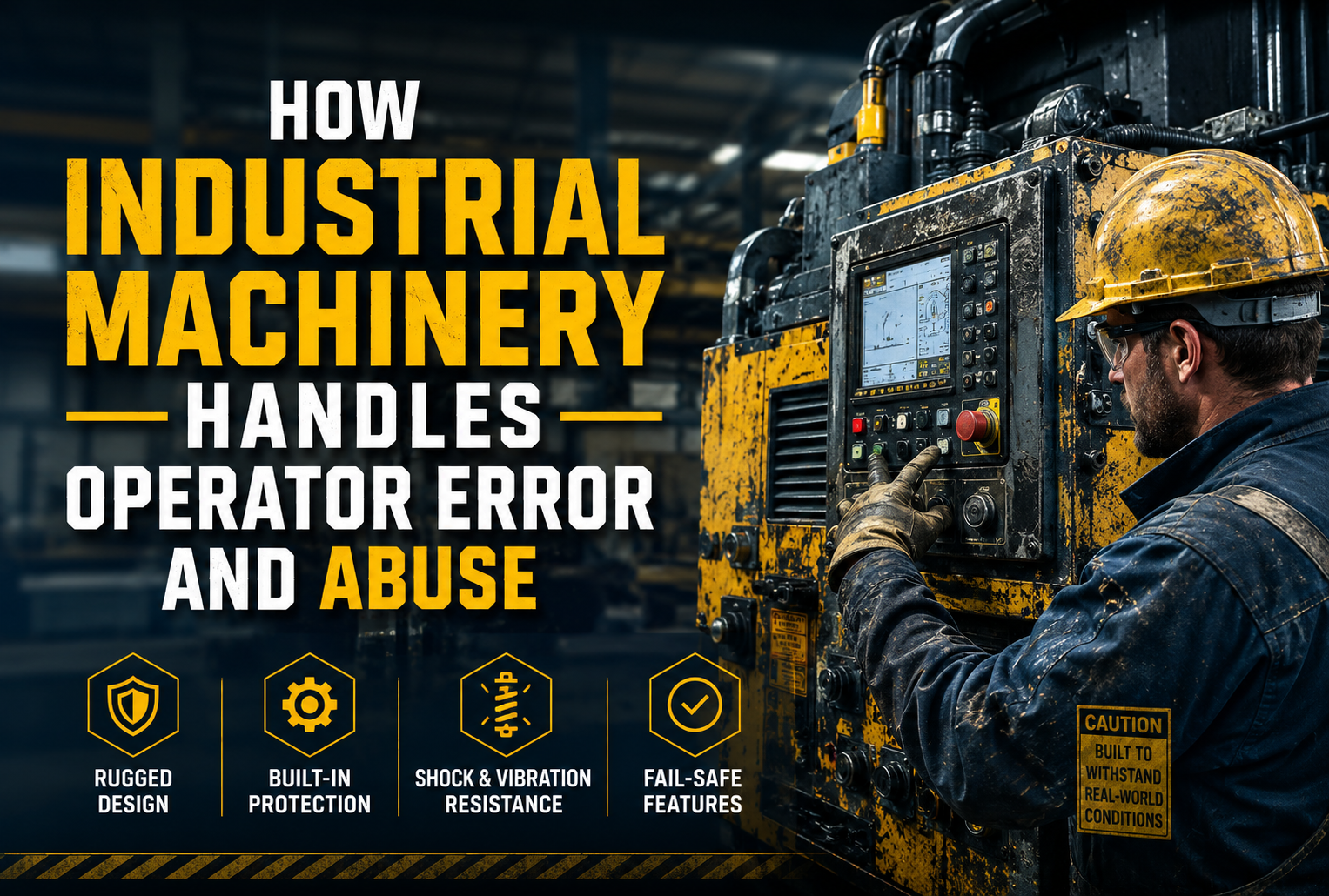
Imagine you’re on your factory floor at 2:00 AM on a Friday. Production is behind schedule, the operator is running on four hours of sleep, and the main conveyor line has just jammed. Instead of following the documented 12-step clearing procedure, they grab a pry bar and apply leverage where they shouldn’t. Twenty minutes later, you’re looking at a bent frame, a stripped gearbox, and a production line that won’t restart until Monday. This is exactly why modern Industrial Machinery is engineered not only for peak performance but also to withstand operator error, unexpected misuse, and the harsh realities of real-world manufacturing environments.
This scenario plays out in Industrial facilities worldwide, and it reveals an uncomfortable truth: every machine will eventually face its worst day. The question isn’t whether your equipment will be pushed past limits, operated under pressure, or subjected to conditions nobody documented. The question is whether you designed for it.
This article explores how thoughtful machine design anticipates misuse through mechanical stops, overload protection, fail-safe logic, and robust structural margins and why designing for the worst day separates good machines from great ones.
1. The Ideal Conditions Fallacy
Every machine leaves the factory optimized for a specific set of operating conditions. Correct feed rates, proper lubrication intervals, trained operators, appropriate ambient temperatures, and loads within rated capacity. The cad design documentation looks perfect, the performance curves are clean, and the design review passes without issue.
Then the machine meets the real world.
Within months sometimes weeks the gap between designed conditions and actual conditions becomes apparent. Operators discover that running 10% over rated capacity produces acceptable output, and nobody stops them. Maintenance intervals slip when production schedules tighten. A new operator who received minimal training makes reasonable-sounding decisions that turn out to be catastrophically wrong.
None of these are malicious acts. They’re the predictable behavior of real humans working under real pressure in real industrial environments. If you’re working with solidworks design tools or developing machinery in-house, this reality has to shape every design decision from the earliest modeling stages.
Designing for equipment misuse isn’t about assuming the worst of your operators—it’s about respecting how machines actually live in the world.
2. Mechanical Stops: The Last Physical Line of Defense
Before electronics, before software, before any intelligent control system—there is geometry. Physical mechanical stops are arguably the most reliable form of overtravel and overload protection because they don’t require power, don’t depend on sensors, and can’t be bypassed by a software update.
A well-designed mechanical stop does more than just prevent a moving component from traveling beyond its intended range. It absorbs impact energy, protects adjacent components from secondary damage, and ideally does so without destroying itself in the process.
Designing stops for actual impact energy matters more than most designers initially appreciate. The relevant calculation isn’t just the force at rated operating speed—it’s the maximum possible kinetic energy at the moment of contact:
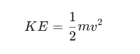
Where m is the combined mass of all moving components and v is the maximum achievable velocity, not the intended operating velocity. These values can differ significantly in systems where motor overrating, control failures, or manual overrides can produce speeds beyond normal operating range.
Hard stops versus compliant stops represent two fundamentally different design philosophies. Hard stops—solid steel-to-steel contact surfaces—are simple, cheap, and extremely reliable. They’re also brutal on structures when hit at speed. Compliant stops using elastomeric buffers, spring-loaded bumpers, or hydraulic dampers absorb energy progressively, reducing peak impact forces on the machine frame.
This is where solidworks design environments prove their worth. You can simulate full limit-of-travel on moving parts, check for collisions at extreme positions, and see which components actually contact when something “bottoms out.” Then you can clearly define stop surfaces, contact faces, and fasteners sized for abuse loads rather than normal operation.
3. Overload Protection: Designing the Weak Link Intentionally
Every mechanical power transmission system has a weakest link. The engineering question is whether that weak link was designed intentionally or discovered accidentally during a catastrophic failure.
Intentional weak links—shear pins, torque limiters, slip clutches, and breakaway couplings—represent one of the most elegant concepts in machine design. The idea is straightforward: identify the most expensive, most difficult to replace, or most safety-critical component in your drivetrain, and then deliberately design something cheaper and easier to replace to fail first when the system is overloaded.
A shear pin in a conveyor drive shaft costs a few dollars and takes minutes to replace. The gearbox it protects might cost thousands and require days of downtime to swap out. When an operator jams the conveyor with an oversized object, the shear pin sacrifices itself so the gearbox doesn’t have to.
Torque limiters and slip clutches offer a more sophisticated version of the same principle. Rather than failing permanently, they slip at a preset torque threshold and re-engage when the overload condition clears. This is particularly valuable in applications where overloads are brief and frequent—a slip clutch can absorb dozens of overload events per shift without requiring maintenance intervention.
Thermal overload protection extends the same philosophy to electrical systems. Motor overload relays, thermal cutouts, and PTC thermistors monitor temperature and interrupt power before winding damage occurs. The key design discipline here is setting protection thresholds that reflect actual motor thermal limits rather than accepting default settings.
When you’re developing these protection systems through, you’re not just drawing parts—you’re defining a hierarchy of what must never fail versus what’s allowed to fail first.
4. Fail-Safe Logic: Defaulting to Safety When Things Go Wrong
Fail-safe design is built on a deceptively simple question: if this component fails, what state should the machine default to? The answer should almost always be the safest possible state—which in most industrial machinery means stopped, de-energized, and with any stored energy released in a controlled manner.
This principle, sometimes called “fail-to-safe” or “de-energize-to-trip,” means that power loss, sensor failure, communication interruption, or control system fault all produce the same result: the machine stops safely.
Interlock logic design is where fail-safe thinking becomes most critical. Safety interlocks—guards, light curtains, emergency stops, pressure switches—need to be wired and programmed so that their failure produces a safe state, not a false-safe state. A guard interlock that fails in the “guard closed” condition is fail-safe. A guard interlock that fails in the “guard closed” condition because the sensor is stuck—while the guard is actually open—is a catastrophic design failure.
Control system architecture matters enormously here. Single-channel safety systems with no diagnostic capability can develop faults that go undetected until the worst possible moment. Dual-channel safety architectures with cross-monitoring detect discrepancies between channels and flag faults before they become incidents.
Modern safety PLCs and safety relay modules implement these architectures in standardized, certifiable ways—but they require deliberate design intent, not just component selection.
5. Structural Margins: Engineering for Unplanned Loads
Structural safety factors exist because real loads are never exactly equal to calculated loads. Material properties vary within specification. Dynamic loads exceed static estimates. Fatigue accumulates over time. And operators exceed rated capacity because nothing immediately bad happens when they do.
For most industrial machinery structural members, safety factors between 2.0 and 4.0 on yield strength are typical, with higher factors applied where dynamic loading, fatigue, or human safety is involved. The relevant stress calculation for combined loading conditions follows the von Mises criterion:
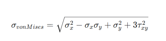
This provides a single equivalent stress value that can be compared against material yield strength, accounting for combined normal and shear stress states common in real structural members.
Designing for abuse loads specifically means thinking beyond normal operating loads to the loads that occur when things go wrong. What happens structurally if the machine is dropped during installation? What if a forklift bumps the frame during repositioning? What if an operator stands on a surface that wasn’t designed as a step?
These aren’t exotic scenarios—they’re routine events in industrial facilities that generate loads that may not appear anywhere in standard design analysis. With a team that uses the right design tools, you can run quick checks on likely abuse scenarios and identify where stresses localize before committing to fabrication.
6. Ergonomics and Mistake-Proofing: Making Wrong Actions Difficult
There’s a category of operator error that isn’t really operator error at all—it’s the predictable result of poor interface design. When controls are confusingly laid out, when status indicators are ambiguous, when maintenance access requires awkward body positions, operators make mistakes not because they’re careless but because the design made mistakes easy.
Thoughtful ergonomic design reduces misuse by making correct operation the path of least resistance:
- Controls grouped and oriented to match the sequence of operation
- Clear visual distinction between normal operating controls and emergency functions
- Maintenance access points positioned so correct procedures are physically easier than incorrect ones
- Status indicators visible from the operator’s natural working position
Mistake-proofing (poka-yoke) takes this further by making incorrect actions physically impossible. If a component has a specific orientation, the mounting should be asymmetric so it can’t be installed backwards. If a maintenance panel provides access to clear jams, it should be sized so a hand can reach the problem area but an entire arm can’t reach dangerous pinch points.
When these principles are properly captured, they become manufacturing requirements rather than suggestions.
How Asset-Eyes Approaches Worst-Day Design
As a machine design company, Asset-Eyes doesn’t treat operator error and abuse as edge cases—we treat them as guaranteed events over a machine’s lifetime. When supporting industrial machinery projects, we integrate abuse-resistant thinking from the earliest concept stages.
Our comprehensive approach includes:
Advanced modeling and simulation using solidworks design to fully model motion limits, guard envelopes, stops, and service access. We run interference checks and stress analysis on abuse scenarios—overloads, jams, mis-operations—to see how structures respond before committing to tooling.
Complete documentation packages through our cad design services and solidworks drafting services that produce clean, reviewable models and drawing sets focused on real-world use, not just nominal operation. Our output captures protection device locations, design rationale notes, and maintenance access requirements.
System-level protection integration ensures that overload protection in one subsystem doesn’t create vulnerabilities in another. We develop cad drawing packages that make stops, guards, interlocks, and critical fasteners unambiguous to everyone involved in fabrication, installation, and maintenance.
Fail-safe logic documentation captured through our services preserves the engineering intent behind safety systems so future modifications don’t inadvertently defeat protection mechanisms.
Whether projects involve new machine development, design reviews of existing equipment, or documentation updates that capture as-built protection systems, we bring the same engineering discipline to abuse resistance that we apply to primary performance requirements.
We’re not just asking “Will it run?” We’re asking “What happens when it jams at 2 AM on a Sunday with the least experienced operator on shift—and how do we make sure everyone walks away and the machine lives to run again?”
Key Takeaways for Resilient Machine Design
Designing for ideal operation is the baseline expectation. Designing for the worst day is where real engineering excellence shows up:
- Assume operator error, rushed decisions, and occasional abuse—they’re inevitable over a machine’s service life
- Use mechanical stops to define hard, safe limits before expensive components take the hit
- Implement overload protection so cheap, predictable elements fail first in a controlled manner
- Build fail-safe logic so loss of power or signal moves the machine to a safe state automatically
- Give critical structures enough margin to survive occasional misuse without hidden damage
- Use ergonomic design to make correct operation easier than incorrect operation
- Leverage comprehensive cad design services and documentation to preserve design intent through fabrication and field service
Machines that survive their worst days don’t get there by accident—they’re engineered that way, on purpose, with protection systems as carefully designed as the production functions they safeguard.
If you’re developing industrial machinery that needs to perform reliably when things go wrong and not just when everything goes right—Asset-Eyes can help you engineer that resilience from day one.
Contact Us Now:
📞 +91 9840895134
Frequently Asked Questions
1. Why do industrial machines fail despite having perfect design calculations and specifications?
Industrial machines fail because they’re designed for ideal conditions rather than real-world operator behavior. While calculations assume correct feed rates and proper maintenance, operators predictably run equipment 10% over rated capacity, skip maintenance intervals under pressure, and make rushed decisions with minimal training. These aren’t malicious acts but inevitable human responses to production pressure that static design margins don’t address.
2. How do mechanical stops protect industrial machinery from operator abuse and overtravel?
Mechanical stops provide the most reliable overtravel protection because they rely on physical geometry rather than power, sensors, or software that can fail. They absorb impact energy and protect adjacent components from secondary damage. Critical design requires calculating maximum possible kinetic energy using $$KE = \frac{1}{2}mv^2$$ where velocity represents maximum achievable speed, not just intended operating velocity, since control failures can exceed normal ranges.
3. What is the difference between hard stops and compliant stops in abuse-resistant machine design?
Hard stops use solid steel-to-steel contact surfaces that are simple, inexpensive, and extremely reliable but transmit brutal peak impact forces directly into machine frames when hit at speed. Compliant stops use elastomeric buffers, spring-loaded bumpers, or hydraulic dampers that absorb energy progressively, significantly reducing peak structural loads. The choice depends on impact energy levels and structural loading tolerance during worst-case overtravel events.
4. How does intentional weak link design protect expensive industrial machinery components from damage?
Intentional weak links deliberately place inexpensive, easily replaceable components—shear pins, torque limiters, slip clutches, breakaway couplings—in the failure path before expensive critical components. A shear pin costing dollars protects gearboxes worth thousands. Torque limiters and slip clutches offer more sophistication by slipping at preset thresholds and re-engaging when overloads clear, handling dozens of overload events per shift without maintenance intervention.
5. What does fail-safe logic mean in industrial machinery control systems?
Fail-safe logic ensures any component failure—power loss, sensor fault, communication interruption, control system error—automatically moves the machine to its safest possible state: stopped, de-energized, with stored energy released controllably. Safety interlocks must be wired so their failure produces genuinely safe states, not false-safe conditions. This “de-energize-to-trip” principle means loss of power or signal always results in safe shutdown rather than continued operation.
6. Why are dual-channel safety architectures necessary for reliable machine protection systems?
Dual-channel safety architectures are necessary because single-channel systems lack diagnostic capabilities, allowing faults to remain undetected until critical emergencies occur. Dual channels with cross-monitoring detect discrepancies between channels and flag faults before they become incidents. Modern safety PLCs and relay modules implement these architectures in standardized, certifiable ways, but they require deliberate design intent rather than just component selection.
7. What structural safety factors should engineers use for machinery subject to operator abuse?
Safety factors between 2.0 and 4.0 on yield strength are typical for industrial machinery structural members, with higher factors for dynamic loading, fatigue, or human safety applications. Combined loading adequacy uses von Mises criterion: $$\sigma_{vm} = \sqrt{\sigma^2 + 3\tau^2}$$ providing equivalent stress comparable against material yield strength. Abuse scenarios—installation drops, forklift contact, unintended stepping surfaces—require analysis beyond standard operating load cases.
8. How does mistake-proofing (poka-yoke) reduce operator error in industrial machinery design?
Mistake-proofing makes incorrect actions physically impossible rather than just discouraged. Asymmetric component mounting prevents backwards installation, maintenance panels sized for hand access but not full-arm reach prevent contact with dangerous pinch points, and controls grouped to match operational sequences reduce confusion. This recognizes that many operator errors result from poor interface design rather than carelessness, making correct operation the path of least resistance.
9. How does SolidWorks design help engineers simulate abuse scenarios before manufacturing?
SolidWorks design environments allow engineers to fully model motion limits, guard envelopes, mechanical stops, and service access geometry before committing to tooling. Engineers can simulate full limit-of-travel conditions, run interference checks at extreme positions, and perform stress analysis on abuse scenarios including overloads, jams, and mis-operations. This digital validation identifies stress localization during worst-case events, enabling proper protection system sizing for abuse loads.
10. How does Asset-Eyes integrate worst-day scenarios into industrial machinery design projects?
Asset-Eyes treats operator error and abuse as guaranteed events over machine lifetimes rather than edge cases, integrating abuse-resistant thinking from earliest concept stages. Their approach combines SolidWorks modeling for motion and abuse simulation, comprehensive CAD drafting services capturing protection device locations and design rationale, system-level protection integration ensuring overload protection doesn’t create vulnerabilities elsewhere, and fail-safe logic documentation preserving engineering intent through fabrication and maintenance.