Picture this scenario: You’re reviewing a pressure vessel design intended for a thermal cycling application. On paper, everything looks perfect. Every stress calculation passes with comfortable margins, material selection follows best practices, and the geometry appears robust. The vessel enters service, repeatedly heating up and cooling down through thousands of thermal cycles. Three years later, cracks begin to appear at nozzle junctions—despite the design meeting all the textbook requirements.
The failure investigation reveals something unsettling: nothing was obviously wrong with the original design approach. The problem wasn’t a calculation error—it was a framing error. The vessel was designed as a static problem when it was actually a fatigue problem in disguise.
If you read most engineering articles about thermal cycling, they’ll walk you through material selection strategies, stress concentration factors, and fatigue curve mathematics as if every design engineer is manually calculating S-N curves from first principles. But when you actually talk to practicing pressure vessel engineers, you hear a different story:
“We don’t hand-calculate all that anymore. We design to ASME. The standards have already baked most of this complexity in.”
That’s the reality. For industrial pressure vessels in North America, thermal cycling isn’t handled as a collection of individual calculations it’s handled through a mature framework of design codes that embed decades of research, failure analysis, and engineering wisdom. This article takes you behind the scenes of that framework: how ASME pressure vessel standards actually treat thermal cycling, what they’re based on, and what you need to understand to use them effectively.
The Standards Reality: How Engineers Actually Design for Thermal Cycling
In theory, designing for thermal cycling could involve manually tracking dozens of variables: coefficient of thermal expansion differences, stress concentration factors at every geometric transition, rainflow cycle counting, cumulative damage calculations using Miner’s Rule, and material fatigue curves adjusted for surface finish, size effects, and environmental conditions.
In practice, for code vessels in the United States, you rarely work from first principles. Instead, you operate within the framework of ASME BPVC Section VIII (Boiler and Pressure Vessel Code), which provides two primary paths:
Section VIII, Division 1 offers “design by rules”—prescriptive formulas for wall thickness, allowable stresses, and construction requirements. For many applications, Division 1’s conservative safety factors provide adequate protection against fatigue without explicit cycle counting or stress range calculations.
Section VIII, Division 2 provides “design by analysis” methodology with explicit fatigue evaluation procedures. When thermal cycling is severe enough that Division 1’s implicit margins aren’t sufficient, Division 2 gives you the analytical tools to demonstrate adequacy through formal fatigue assessment.
The key insight is that these standards represent crystallized lessons from decades of vessel failures, laboratory testing, and service experience. When you say “this vessel is designed for thermal cycling,” you’re typically saying: “We’ve applied ASME Section VIII provisions appropriate to cyclic service, using its embedded fatigue methodology and design curves.”
Understanding what those provisions actually do and what assumptions they’re built on—is where real engineering competence lives.
ASME Section VIII: Two Paths, Different Depth
The choice between Division 1 and Division 2 isn’t arbitrary it reflects how severe your thermal cycling conditions are and how much analytical depth is needed to demonstrate adequacy.
Division 1: Conservative Rules for Moderate Cycling
Division 1 works through prescriptive formulas and conservative allowable stresses that already include safety factors on both yield strength and ultimate tensile strength. For vessels with moderate thermal cycling typical startup/shutdown cycles in steady industrial service—these built-in margins often provide adequate protection against fatigue without explicit calculation.
The code provides guidance on when thermal cycling becomes severe enough to require more rigorous analysis. Generally, this happens when you have:
- High cycle counts (thousands of significant thermal cycles)
- Large temperature swings (typically above 200°F differential)
- Rapid thermal transients that create severe gradients
- Complex geometry with multiple nozzles and attachments
Division 2: Explicit Fatigue Analysis When It Matters
Division 2 is where the real fatigue methodology lives. Instead of relying on conservative safety factors to implicitly handle cyclic loading, Division 2 provides explicit procedures for:
- Stress analysis using finite element methods
- Classification of stresses (primary membrane, primary bending, secondary, peak)
- Fatigue evaluation using design fatigue curves and usage factors
The fatigue screening criteria in Part 5 of Division 2 are particularly important—they establish threshold conditions that determine whether formal fatigue analysis is required. These thresholds aren’t arbitrary; they represent conditions below which fatigue damage accumulation is unlikely to be life-limiting over normal service periods.
Design Fatigue Curves: Where Decades of Testing Live
When Division 2 fatigue analysis is required, the central tool is the design fatigue curve—the relationship between stress amplitude and allowable cycles found in Annex 3-F. These curves represent one of the most data-rich elements of the entire code.
The curves start with laboratory fatigue testing on smooth specimens, then undergo several adjustments to reflect real-world conditions:
Stress concentration effects account for the geometric discontinuities present in real vessels—weld toes, nozzle junctions, thickness transitions. The code applies fatigue strength reduction factors that modify smooth-bar data to reflect these realistic stress concentrations.
Surface finish and environmental corrections adjust for the difference between polished laboratory specimens and real vessel surfaces with weld profiles, machining marks, and operating environments.
Statistical treatment positions the design curves at conservative locations relative to experimental scatter. The ASME curves typically represent lower-bound behavior with additional safety factors applied to both stress and cycle axes.
The mathematical framework follows Miner’s Rule for cumulative damage:
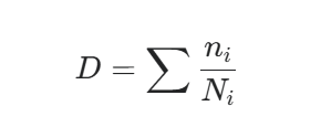
where ni is the actual number of cycles at stress amplitude i, and Ni is the allowable number of cycles from the design curve. The code requires D ≤1.0 for acceptable fatigue life.
For thermal stress calculation, the fundamental relationship remains:
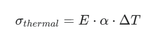
where E is elastic modulus, alpha is coefficient of thermal expansion, and ΔT is the temperature change. This thermal stress develops independently of internal pressure and cycles with every heat-up and cool-down event.
The Engineering Workflow: From Standards to Reality
Modern pressure vessel design for thermal cycling involves an integrated workflow that bridges standards compliance, digital modeling, and manufacturing documentation. Understanding this workflow helps explain where different software tools fit and why comprehensive cad design services are essential.
3D Modeling and Analysis Integration
The process typically starts with detailed 3D modeling using appropriate CAD platforms. While SolidWorks design is widely used for its parametric capabilities and strong integration with analysis tools, other platforms like Autodesk Inventor, Creo, or NX may be preferred depending on specific project requirements or client workflows. The key is developing clean, parametric geometry that can feed effectively into finite element analysis.
For Division 2 stress analysis, the 3D model exports to FEA platforms like ANSYS Mechanical or Abaqus, which excel at thermal-structural coupling analysis. These tools can simulate the exact temperature distributions and stress concentrations that Division 2 fatigue procedures require, allowing engineers to extract linearized stresses at critical locations and compare them against code allowables.
Documentation and Fabrication Integration
The analyzed geometry must then become manufacturable hardware through comprehensive drawing packages. This is where professional cad drafting services become critical—the drawings must capture not just nominal dimensions but the specific geometric requirements that thermal fatigue analysis depends on: fillet radii, taper angles, weld profiles, and material specifications.
A complete general assembly drawing set for a thermally cycled vessel includes design intent information that static vessels don’t require: cycle count assumptions, temperature range specifications, and references to the specific code edition and analysis methods used. This documentation ensures that future modifications or fitness-for-service assessments have access to the original design basis.
What the Standards Don’t Handle For You
Understanding the boundaries of what ASME provides is as important as understanding its capabilities.
Operating Cycle Definition
The standards provide the analytical framework, but they don’t define your actual operating cycles. How many startups per year? What are the temperature ramp rates during heatup? Are there upset conditions that generate additional stress cycles? These inputs come from process engineering and operations—and if they’re poorly defined, even rigorous code compliance won’t ensure adequate fatigue life.
Environmental Effects Beyond Code Scope
The design fatigue curves include adjustments for typical industrial environments, but aggressive process conditions—high-temperature corrosion, hydrogen service, caustic environments—can accelerate fatigue crack growth beyond code predictions. Additional assessment may be required using standards like API 579-1/ASME FFS-1 for fitness-for-service evaluation.
Design Optimization Decisions
The code tells you whether a design meets minimum requirements. It doesn’t tell you how to optimize an inadequate design. That requires understanding the underlying fatigue mechanics well enough to identify which changes geometry modifications, material upgrades, support configuration adjustments will most effectively improve performance.
The Broader Standards Ecosystem
ASME Section VIII operates within a broader framework of interconnected standards that practicing engineers need to understand:
API 579-1/ASME FFS-1 governs fitness-for-service assessment of vessels already in operation, providing methods for evaluating remaining fatigue life and making run/repair/replace decisions.
ASME Code Case 2695 offers alternative fatigue assessment procedures using structural stress methods, which can provide more accurate results for welded joints by reducing mesh sensitivity in finite element analysis.
WRC Bulletins (Welding Research Council) provide supplementary guidance on specific topics like nozzle flexibility analysis and local stress evaluation at attachments—areas where the base code provides methodology but practitioners benefit from additional technical guidance.
ASME B31.3 governs connected process piping, and its fatigue provisions must be coordinated with vessel analysis, particularly for nozzle connections where vessel and piping fatigue lives interact.
How Asset-Eyes Approaches Standards-Compliant Thermal Cycling Design
As a machine design company with deep experience in pressure vessels and industrial equipment, Asset-Eyes understands that successful thermal cycling design requires bridging the gap between rigorous standards compliance and practical manufacturing reality.
Our approach integrates several key capabilities:
Multi-Platform CAD and Analysis Expertise
We work with the software platforms that best serve each project’s specific requirements—whether that’s SolidWorks design for parametric modeling and assembly management, ANSYS for thermal-structural analysis, or specialized pressure vessel tools for code compliance verification. Our cad design services produce models that support both design development and the formal analysis workflows that Division 2 requires.
Standards-Focused Documentation
Our cad drafting services generate drawing packages that capture the design intent behind m provisions not just the geometry, but the cycle count assumptions, temperature specifications, and code references that make vessels assessable throughout their service life. We understand that a thermally cycled vessel’s documentation is fundamentally different from a static vessel’s drawing set.
Code Compliance Integration
We don’t just apply software tools—we apply the engineering intelligence behind ASME requirements. Our team understands when Division 1 implicit margins are sufficient versus when Division 2 explicit analysis is required, how to properly extract and linearize stresses for code evaluation, and how to document the design basis so future engineers can make informed modification decisions.
The difference between a vessel that performs reliably through decades of thermal cycling and one that develops premature fatigue cracking often comes down to how rigorously the ASME framework was applied during design and how completely that analysis was preserved in the final documentation.
Key Takeaways for Engineers
Modern pressure vessel design for thermal cycling isn’t about manually calculating every fatigue parameter—it’s about intelligently applying a mature standards framework that has already organized that complexity:
- ASME Section VIII Division 1 provides conservative design rules adequate for moderate thermal cycling through implicit safety factors
- Division 2 offers explicit fatigue analysis methods when cycling conditions exceed Division 1 thresholds
- Design fatigue curves in Division 2 represent decades of experimental data adjusted for real-world stress concentrations and environmental effects
- Fatigue screening criteria determine when formal analysis is required, based on cycle counts, temperature differentials, and geometric complexity
- The broader standards ecosystem—API 579, WRC Bulletins, ASME Code Cases—provides supplementary guidance for specific situations the base code doesn’t fully address
- Quality of cycle definition going into the analysis is as critical as the rigor of the analytical methods themselves
The standards represent accumulated engineering knowledge about how vessels actually fail under cyclic loading. Understanding what they’re based on—not just how to apply them mechanically—enables engineers to use them intelligently rather than just procedurally.
If you’re working on pressure vessels or thermally cycled equipment and want to ensure your design approach, analysis methods, and documentation align with ASME expectations while supporting efficient manufacturing, Asset-Eyes can serve as your design partner throughout the process—from initial modeling through code-compliant documentation.
Contact Us Now:
📞 +91 9840895134
Frequently Asked Questions
1. Why do pressure vessels fail under thermal cycling even when static design calculations appear correct?
Pressure vessels fail under thermal cycling because they’re designed as static problems when they’re actually fatigue problems in disguise. Even when stress calculations pass with comfortable margins and materials follow best practices, repeated heat-up and cool-down cycles create cumulative fatigue damage that static design margins don’t address. Cracks typically appear at nozzle junctions after years of thermal cycling service.
2. How does ASME Section VIII handle thermal cycling in pressure vessel design?
ASME Section VIII handles thermal cycling through two primary paths that embed decades of research and failure analysis. Division 1 uses conservative “design by rules” with safety factors that implicitly protect against moderate cycling. Division 2 provides explicit “design by analysis” methodology with formal fatigue evaluation procedures when cycling conditions are severe enough to exceed Division 1’s built-in margins.
3. When is ASME Division 2 explicit fatigue analysis required instead of Division 1 for thermal cycling?
Division 2 explicit fatigue analysis is required when thermal cycling exceeds Division 1’s conservative thresholds. This typically occurs with high cycle counts involving thousands of significant thermal cycles, large temperature swings above 200°F differential, rapid thermal transients creating severe gradients, or complex geometry with multiple nozzles and attachments. Division 2’s fatigue screening criteria establish these specific threshold conditions.
4. What are ASME Division 2 design fatigue curves and how do they account for real-world conditions?
ASME Division 2 design fatigue curves in Annex 3-F relate stress amplitude to allowable cycles based on decades of laboratory testing data. They start with smooth specimen results, then apply fatigue strength reduction factors for geometric discontinuities, surface finish corrections for real vessel conditions, and statistical treatment positioning curves at conservative lower-bound locations with additional safety factors on both stress and cycle axes.
5. How is cumulative fatigue damage calculated for thermally cycled pressure vessels?
Cumulative fatigue damage follows Miner’s Rule: $$D = \sum \frac{n_i}{N_i}$$ where $$n_i$$ represents actual cycles at stress amplitude i and $$N_i$$ represents allowable cycles from design curves. The code requires D ≤ 1.0 for acceptable fatigue life. Thermal stress is calculated as $$\sigma = E \cdot \alpha \cdot \Delta T$$, cycling independently with every temperature change regardless of internal pressure.
6. What critical information must engineers provide that ASME standards don’t define for thermal cycling?
ASME provides the analytical framework but doesn’t define actual operating cycles. Engineers must establish how many startups occur per year, temperature ramp rates during heatup, and upset conditions generating additional stress cycles. Poorly defined operating cycle inputs from process engineering can undermine even rigorous code compliance, making cycle definition as critical as analytical rigor.
7. How does 3D CAD modeling integrate with ASME Division 2 fatigue analysis workflows?
3D CAD modeling provides clean, parametric geometry that exports directly into finite element analysis platforms like ANSYS Mechanical or Abaqus for thermal-structural coupling analysis. These FEA tools simulate exact temperature distributions and stress concentrations required by Division 2, allowing engineers to extract linearized stresses at critical locations and compare them against ASME code allowables for fatigue evaluation.
8. What limitations do ASME fatigue provisions have for aggressive service environments?
ASME design fatigue curves include adjustments for typical industrial environments but don’t fully capture aggressive conditions like high-temperature corrosion, hydrogen service, or caustic environments. These conditions can accelerate fatigue crack growth beyond code predictions, requiring additional assessment using standards like API 579-1/ASME FFS-1 for fitness-for-service evaluation and remaining life calculations.
9. What broader standards ecosystem supports ASME Section VIII for thermal cycling applications?
The broader standards ecosystem includes API 579-1/ASME FFS-1 for fitness-for-service assessment of operating vessels, ASME Code Case 2695 offering alternative structural stress methods for welded joints, WRC Bulletins providing supplementary guidance on nozzle flexibility and local stress evaluation, and ASME B31.3 governing connected process piping that must coordinate with vessel fatigue analysis.
10. How does Asset-Eyes approach standards-compliant thermal cycling design for pressure vessels?
Asset-Eyes integrates multi-platform CAD expertise, thermal-structural analysis capabilities, and deep ASME code compliance knowledge. The team works with SolidWorks, ANSYS, and specialized pressure vessel tools, producing models supporting both design development and Division 2 analysis workflows. They generate documentation capturing cycle count assumptions, temperature specifications, and code references essential for vessels’ entire service life assessment.