What Does UL 508A Panel Documentation Actually Require?
UL 508A panel documentation requires a complete, internally consistent set of drawings and data that lets an inspector verify component ratings, short-circuit current rating, wiring methods, spacing, grounding, and nameplate markings without relying on the physical panel alone to tell the story. In practice, the documentation isn’t a supplement to certification it functions as the certification itself. A panel built correctly but documented incompletely fails inspection just as surely as a panel with a genuine wiring defect.
Why Documentation Is Effectively the Inspection
Most panel builders think of UL 508A as a physical check: an inspector arrives, looks at the panel, and approves or rejects it. That understanding is incomplete in a way that creates expensive surprises. A UL field representative reviewing a 508A panel isn’t primarily judging whether the panel looks right they’re verifying that the documentation supports the compliance claim, then confirming the physical panel matches that documentation. A panel that’s fabricated flawlessly but whose drawings contain gaps, inconsistencies, or missing calculations will still fail, and the failure gets attributed to documentation, not fabrication. That distinction matters because it tells you where quality control actually needs to live — before fabrication starts, not after an inspector flags a deficiency.
The UL 508A Documentation Framework
Rather than treating UL 508A as a monolithic requirement, it’s more useful to break it into four areas that account for the overwhelming majority of what inspectors check and where documentation most often falls short.
1. Component Traceability and Ratings
Every component in the power circuit needs to be documented with its manufacturer, part number, and UL listing or recognition status — a generic line item like “20A circuit breaker” isn’t sufficient. If you’re using UL Recognized components rather than UL Listed ones, your documentation needs to demonstrate that the component’s specific conditions of acceptability have been met in your design. This requirement creates a direct link between your component library and your documentation quality: shops with a well-organized, current library of manufacturer data produce compliant packages faster and with fewer inspection findings than shops reconstructing component ratings project by project.
2. Short-Circuit Current Rating (SCCR) Documentation
The SCCR is the panel’s rated ability to withstand available fault current at its point of installation, and it must be calculated, documented, and reflected on the nameplate. Under UL 508A, the panel’s overall SCCR is generally set by the lowest-rated component in the fault current path unless a tested combination or series-rated system establishes a higher value. Where a transformer feeds the panel, the secondary fault current is a common piece of that calculation, generally expressed as:
Iₛc = IᴇFLA × 100 / Zₚct
where I₍FLA₎ is the transformer’s rated secondary full-load current and Zₚct
is the transformer’s percent impedance. What your documentation needs to show is not just the final SCCR value on the nameplate, but the calculation or component combination that supports it a nameplate showing 65 kA next to a BOM containing a component rated for only 10 kA is a documentation inconsistency that stops an inspection cold, regardless of how the panel was actually built.
3. Physical Layout, Spacing, and Wire Routing
UL 508A specifies exact clearance requirements between bare live parts of opposite polarity and between live parts and grounded metal. A schematic alone can’t demonstrate compliance here — you need a scaled physical layout drawing showing where components, wire duct, and terminal blocks sit relative to each other, so field installers and shop technicians don’t inadvertently violate spacing rules during assembly.
4. Nameplate and Labeling Specifications
The standard requires specific information permanently marked on the panel: manufacturer name, electrical ratings (voltage, phase, frequency, full-load current), SCCR, and enclosure environmental rating (Type 4X, for example). Your documentation needs to include a precise layout and exact text specification for every label — leaving this to shop-floor judgment guarantees inconsistencies and invites findings.
Signs Your Documentation Process Is Failing
You rely on tribal knowledge for compliance: Engineers know how to build a safe panel, but there’s no standardized checklist or CAD-driven process generating SCCR calculations or component lists consistently.
Inspectors frequently ask for supplemental information: If a UL inspector needs to request data sheets or calculation proof during an inspection, the drawing package was incomplete going in.
The shop floor is making compliance decisions: Technicians are choosing wire sizes or fuse types on the fly because the engineering drawings didn’t specify them.
Component substitutions aren’t reflected in documentation: A specified part is unavailable, a compliant substitute is used on the floor, and the BOM and schematic aren’t updated before inspection — creating a mismatch between the physical panel and the paperwork.
Signs Your Documentation Process Is Working
Your CAD system drives compliance, not the other way around: An intelligent electrical design platform (EPLAN, AutoCAD Electrical, SolidWorks Electrical) with a validated component database pulls in UL ratings automatically and generates BOMs directly from the schematic.
Calculations are a standard deliverable, not an afterthought: SCCR documentation is a routine page in every drawing package, addressed during component selection rather than bolted on at the end.
Inspections are a formality: Panels pass on the first attempt because the documentation package proactively answers every question an inspector might ask.
What a Complete UL 508A Documentation Package Includes
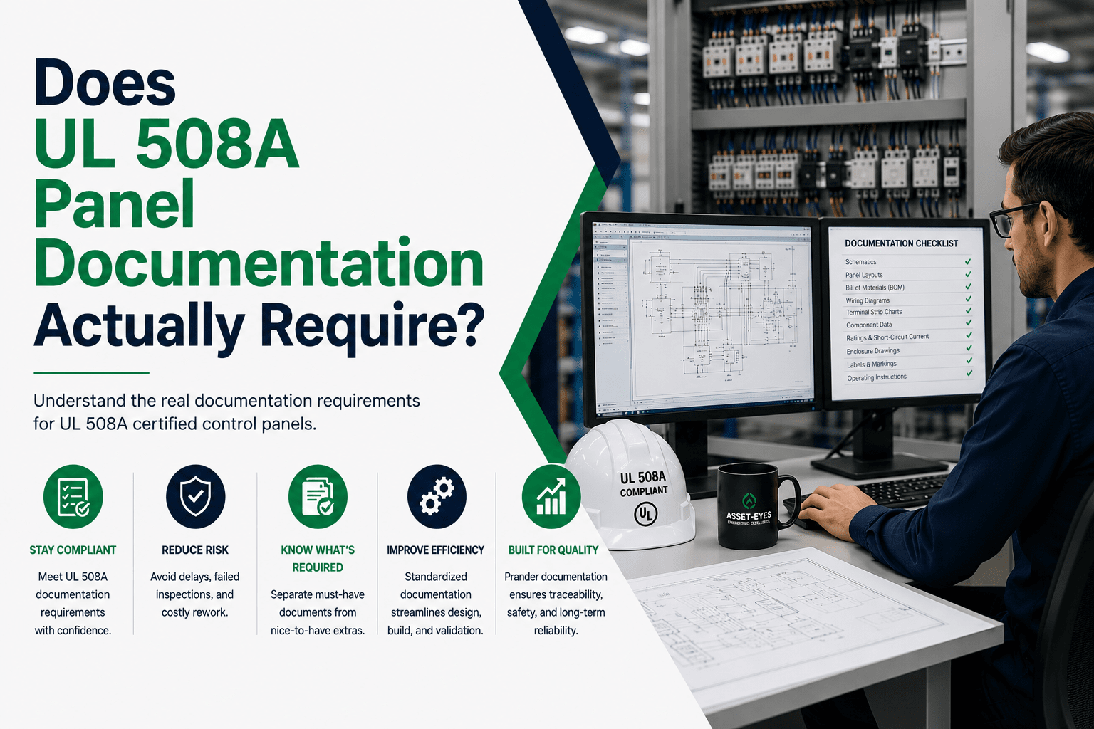
A compliant package typically includes:
- Schematic diagrams showing all power and control circuits, component identification with model numbers and ratings, conductor sizing, and complete grounding paths
- A panel layout drawing showing physical component placement, clearances, and mounting details
- A bill of materials with manufacturer, model number, and relevant ratings for every component
- A wire list generated from the schematic, not created independently, to avoid conductor-size mismatches
- A terminal plan coordinating internal schematic connections with field wiring assignments
- SCCR calculation or component combination documentation supporting the nameplate rating
- Nameplate data consistent with every other document in the package
No item on this list is optional — each serves a specific verification function during inspection, and the absence of any one creates a gap the inspector can’t work around.
How Asset-Eyes Supports UL 508A-Compliant Documentation
Asset-Eyes produces complete electrical panel documentation packages for control panel builders and system integrators who need standards-compliant deliverables without carrying full-time electrical design staff for every project. Our team works with a practical understanding of UL 508A requirements — not just CAD proficiency — producing schematics, layouts, wire lists, BOMs, and SCCR documentation that are internally consistent and inspection-ready, following your component preferences and project standards. Whether you need overflow support during a peak phase or ongoing documentation capacity, we integrate with your existing workflows and deliver packages your shop floor and inspection team can work from directly.