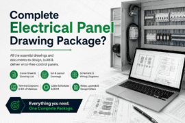
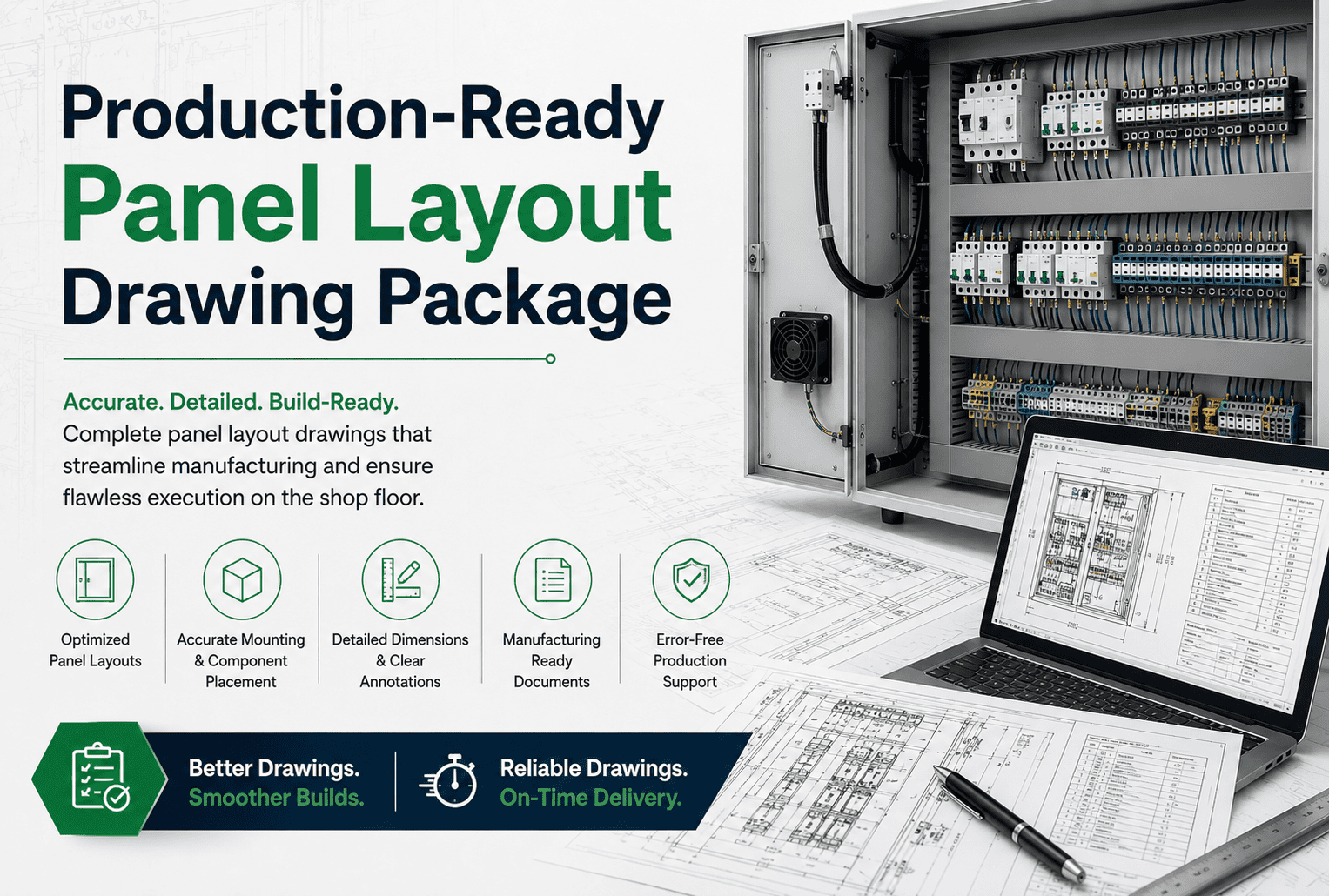
What’s Included in a Production-Ready Panel Layout Drawing Package?
A production-ready panel layout drawing package includes the panel layout drawing, electrical schematics, a bill of materials, a wire list, a terminal plan, and nameplate and SCCR documentation but the deciding factor isn’t whether all six exist, it’s whether they agree with each other at every shared reference point. A schematic that specifies a terminal block the layout hasn’t physically placed, or a BOM that lists a part the wire list never references, isn’t a documentation gap; it’s a fabrication risk waiting to surface on the shop floor. The rest of this page breaks down what each of the six deliverables must contain and why internal consistency, not raw completeness, is the standard that actually determines whether a package is ready for production.
The Completeness vs. Consistency Distinction
Most panel shops define “complete” as “we have all six documents.” That bar is too low. A production-ready package requires every document to agree with every other document at every point they reference the same thing: a wire number on the schematic must appear identically on the terminal plan and the wire list; a device tag on the layout drawing must match the tag on the schematic and the part number on the BOM; SCCR documentation must reflect the components actually specified in the BOM, not a generic calculation performed in isolation. When these documents are produced separately a schematic by one engineer, a BOM maintained on a parallel spreadsheet, a terminal plan updated by hand after the schematic changes small inconsistencies accumulate silently and surface on the bench at the worst possible moment, usually mid-build or at inspection. A package generated from a single source of truth cannot drift this way; a package assembled from disconnected documents always eventually does.
The Six Components of a Production-Ready Package
1. Panel Layout Drawing
The layout is the physical map of the enclosure: where every device mounts, how wire duct routes between them, and whether the design actually fits the specified footprint. A production-ready layout validates component spacing, creepage and clearance requirements, and thermal management against real dimensions rather than estimates, and it uses the same device tags as the schematics and BOM. If the layout was finalized before component selection was locked, it isn’t production-ready regardless of how clean it looks.
2. Schematics
Schematics are the logical map of the panel power distribution, control circuits, I/O, and safety logic. A production-ready schematic set uses one wire-numbering convention throughout, assigns a unique tag to every device, and covers every circuit without placeholder pages. Page count is not a quality signal; a fifteen-page set that is internally complete is more useful to a fabricator than a thirty-page set with undefined wire numbers.
3. Bill of Materials
A production-ready BOM is generated directly from the schematic, not maintained on a parallel spreadsheet. Every component in the drawings appears in the BOM with a manufacturer part number, and every line in the BOM traces back to a drawing reference the two cannot diverge without a deliberate design change. Long-lead-time items should be flagged explicitly so procurement can act before fabrication is scheduled to start, not after.
4. Wire List
The wire list is the fabricator’s routing guide: what connects to what, through what path, in what gauge and color. A production-ready wire list is generated from the schematic, so every connection shown on the drawing appears in the list with a matching wire number. A wire list maintained independently is a chronic source of discrepancy a late schematic change updates the drawing but not the list, and the assembler follows the list.
5. Terminal Plan
The terminal plan documents every terminal block: numbers, connections on both sides, and any jumper configuration. It must be consistent with both the schematic and the wire list the same terminal number should refer to the same physical connection in all three documents. Terminal plans drafted from memory or copied from a prior job without verification are a reliable source of field wiring errors.
6. Nameplate and SCCR Documentation
Nameplate data specifies the exact text and format of every required label, so the shop floor applies markings that match the drawings rather than making a judgment call. SCCR documentation demonstrates that the panel’s short-circuit current rating has been calculated for the actual installed components, not a generic assumption. Both are inspection-critical: a UL 508A inspector cross-references nameplate text and SCCR calculations against the physical build, and if either is missing or inconsistent with the rest of the package, the inspection fails on documentation rather than on fabrication quality.
Signs a Package Is Not Actually Production-Ready
- The BOM predates the final design revision and hasn’t been reconciled against it.
- Terminal numbers don’t match between the schematic and the terminal plan on more than one or two pages.
- Wire numbers diverge between the schematic and the wire list for any circuit modified after initial drafting.
- The layout shows components that were substituted during procurement without an updated drawing.
- SCCR documentation references a generic calculationrather than the specific components in the current BOM.
- Nameplate text is marked “TBD”or left to the shop floor’s discretion.
What Outsourced Documentation Should Deliver
A qualified external drafting team should produce a package that goes directly to your shop floor without rework: schematics and layouts drawn in your CAD platform using your existing symbol library and templates; wire numbers and device tags that follow your conventions exactly; a BOM and wire list generated automatically from the schematic rather than reconciled by hand; and revision-controlled files delivered into your existing folder or PDM structure, ready for immediate use.
How Asset-Eyes Delivers Production-Ready Panel Packages
Asset-Eyes builds complete panel drawing packages inside your CAD environment, using your symbol libraries and naming conventions, with BOMs and wire lists generated directly from the schematic and every package run through a cross-reference check before delivery. Your shop floor receives a set that agrees with itself, not six individually complete documents that still require reconciliation before fabrication can start.