Picture the moment a facility project starts to feel real. Steel is up, major equipment is on its way, and the schedule finally looks like it’s holding. Then someone walks the site with a tape measure and finds that the maintenance crane runway needs a straight path exactly where a roof truss sits, or that the chilled-water header and the main cable tray both want the same six feet of overhead space. Work stops. Change orders start. Everyone starts asking the same question: how did nobody catch this earlier?
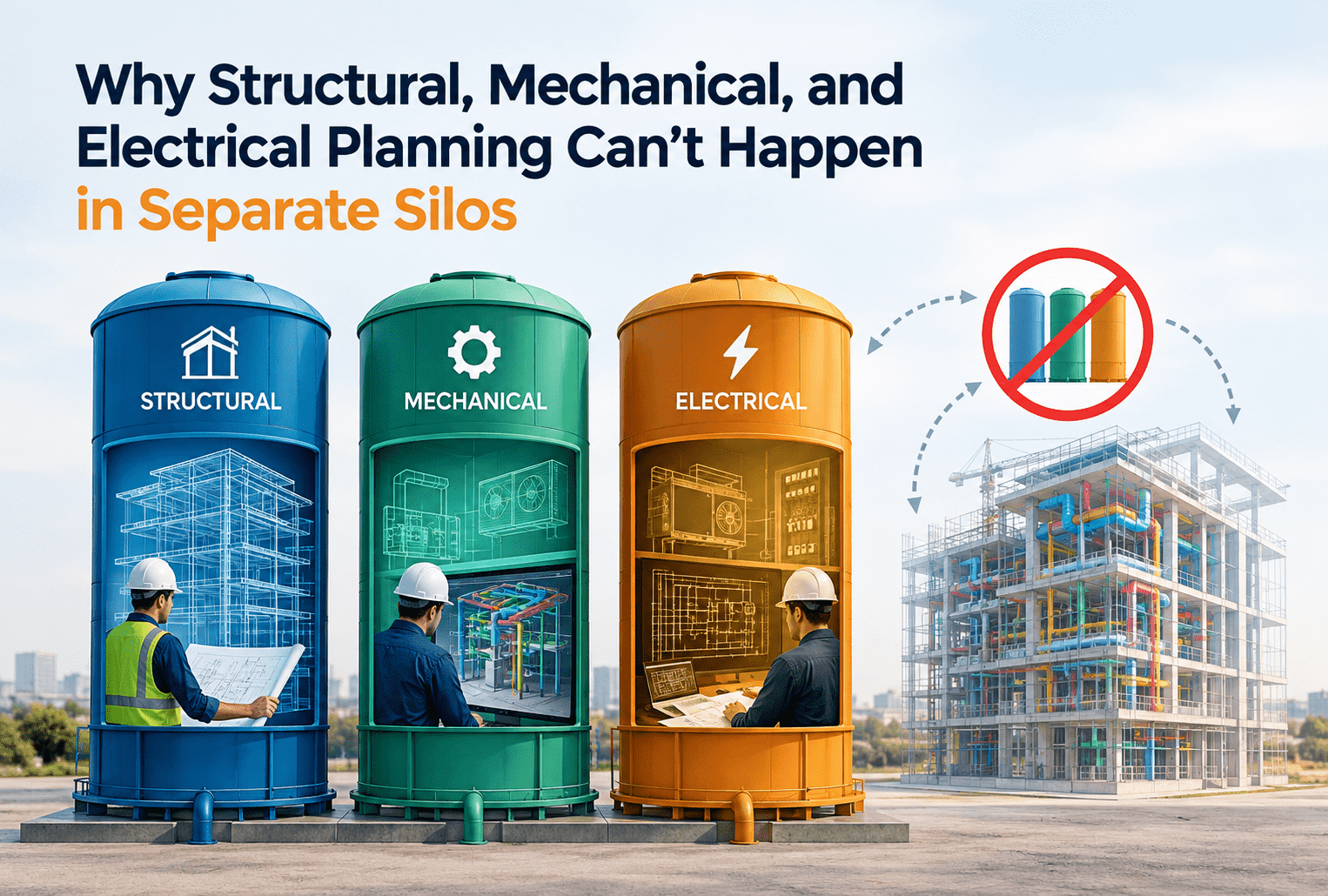
The honest answer is usually that structural, mechanical, and electrical planning moved forward in parallel, not together. As a machine design company that provides engineering design services to manufacturers across a wide range of industries, we see this pattern often enough that it’s worth explaining clearly: integrated facility system planning exists precisely because these three infrastructure decisions constrain each other, constantly. Plan them separately, and you don’t remove the conflicts you just postpone discovering them until construction, which is the single most expensive place to find a design problem.
This article walks through why these systems can’t be designed in isolation, where the most common and costly conflicts actually show up, what a genuinely coordinated planning process looks like, and how that coordination functions as a cost-avoidance strategy rather than an extra layer of process.
Why These Three Systems Can’t Be Designed in Isolation
Facility design isn’t three separate checklists structural, mechanical, electrical that get stitched together at the end. It behaves more like a three-dimensional puzzle where every piece has weight, height, clearance, and a connection point that has to land somewhere specific.
Structural elements determine what can actually be suspended, floor-mounted, or wall-hung, and where. Mechanical systems process piping, HVAC, utility headers need continuous runs, slope, and access, which means they claim space aggressively. Electrical infrastructure needs panel locations, cable routing, and segregation from heat and moisture, and it has to connect to equipment wherever that equipment ends up sitting. None of these disciplines can finalize their own layout without knowing what the other two are doing in the same physical volume.
When they’re designed independently anyway, the same overhead zone or the same equipment bay effectively gets allocated twice. Somebody has to lose that argument and it’s almost always resolved in the field, at the worst possible time, rather than in a model, at the cheapest possible time.
Where the Conflicts Actually Show Up
A few specific zones account for most of the expensive surprises we see in facility projects:
- Overhead space. Structural beams, crane clearances, HVAC ductwork, process piping, cable trays, and fire protection lines all compete for the same ceiling volume. Without coordinated planning, that volume gets treated as available real estate by three different teams at once.
- Equipment footprint versus structural reality. Equipment doesn’t just have a footprint — it has an operational envelope for normal running, a maintenance envelope for service access, and staging space for material in and out. Equipment footprint modeling has to incorporate all three, or a column grid that looks fine on paper ends up blocking a motor pull or a conveyor path.
- Mechanical and electrical coupling. Utility connection planning and electrical system design are two sides of the same decision. If power, controls, and utility routing aren’t planned against the same equipment layout, you end up with long, awkward cable runs or panels dropped into whatever space happens to be left over.
- Safety and egress. Emergency access routes, safety equipment locations, and hazard-area identification aren’t a layer applied after the layout is finished they constrain where equipment, panels, and utilities can go in the first place. Safety and egress layout development has to happen alongside equipment layout design, not after it, because it ties directly to life-safety and regulatory outcomes.
Resolving these zones properly is where equipment clearance analysis earns its place in the process. It isn’t just checking whether a machine fits in a room it’s confirming that the equipment fits alongside the structural elements around it, the utility connections it needs, the maintenance access it requires, and the egress paths that have to stay clear no matter what else is happening in that space.
Why the Conflicts Usually Surface During Construction
Most teams already talk to each other. The real gap isn’t communication it’s coordination depth. Coordination often happens only at a high level: room sizes, major corridors, total loads. Each discipline develops its own drawings, and cross-checks are limited to a visual overlay rather than a true clash check. Two-dimensional views get used to catch problems that are fundamentally three-dimensional, especially anything overhead. Future phases get “allowed for” in a note rather than actually modeled.
So the real discovery process ends up happening on site: the steel erector finds the overhead clash, the piping contractor finds the impossible slope, the electrical crew finds there’s no clean path left for cable tray. At that point, you’re not solving a design problem anymore you’re solving it with steel already up, materials already ordered, and a schedule that assumed the space would be ready.
This is the core logic behind treating integrated facility system planning as a cost-avoidance strategy rather than a nice-to-have. The further downstream a conflict is discovered, the more it costs to fix, because more decisions, materials, and labor have already been committed around the original flawed layout. Finding and resolving that same conflict in a shared 3D facility model, before anything is ordered, is simply a cheaper place to have the disagreement.
What Genuine Coordination Looks Like
In practice, coordinated facility planning means bringing structural, mechanical, electrical, and safety systems into one shared model rather than three separate drawing sets. That typically includes:
- Equipment layout design that’s checked directly against the structural grid, not fitted around it after the fact
- 3D facility modeling to identify and resolve overhead and spatial conflicts before they’re physical
- Utility connection planning that treats cable tray and piping corridors as shared systems, not leftover space
- Comprehensive facility design documentation that captures the resolved layout clearly enough for construction and installation teams to trust it
Once a conflict is visible in a coordinated model, it usually takes a design change and a few clicks to resolve not a blowtorch, a change order, and a week of lost schedule in the field.
Where Asset-Eyes Fits In
Asset-Eyes is a machine design company offering engineering design services to manufacturers across a broad range of industries plant layout and facility design is one of the domains where that coordination work matters most. In this space, we help translate process requirements, equipment specifications, and safety goals into layouts where structural, mechanical, and electrical systems are checked against each other before they’re built into anything.
That means modeling equipment footprints with their full operational and maintenance envelopes, coordinating utility connection planning alongside equipment layout, using 3D facility modeling to catch overhead and spatial conflicts, and developing safety and egress layouts that respect hazard zoning from the start. We also produce comprehensive facility design documentation to support construction and installation activities work we support with CAD design services and modeling tools, though the tools are simply how the coordination gets proven, not the point of the work itself.
To be clear about scope: this is layout design and documentation that supports construction, installation, and facility management we don’t perform the construction or installation ourselves, and we don’t issue regulatory sign-off on safety or egress compliance. What we do is make sure that by the time your project moves into execution, the conflicts that would otherwise surface in the field have already been found and resolved on the design side.
Key Takeaways
- Structural, mechanical, and electrical decisions constrain each other constantly — they can’t be finalized independently and merged later
- Overhead space, equipment footprint versus structural grid, mechanical-electrical coupling, and safety/egress routes are where most costly conflicts concentrate
- Conflicts usually surface during construction not because teams don’t talk, but because coordination happens at too shallow a level to catch true spatial clashes
- Coordinated planning equipment layout design, clearance analysis, 3D facility modeling, utility connection planning, and safety/egress layout, tied together in comprehensive documentation is a cost-avoidance strategy, not an added process step
If you’re planning a new line, an expansion, or a facility reconfiguration and want fewer surprises once installation begins, we’d welcome the conversation.
Schedule a discovery call with us today: [Calendly — Welcome to Asset-Eyes Infomatics]
Partner With Our Design Team
📞 +91 9840895134
Why can’t structural, mechanical, and electrical planning happen in separate silos?
Structural, mechanical, and electrical systems can’t be designed separately because each discipline constrains the others within the same physical volume. Structural elements determine what can be suspended or floor-mounted, mechanical systems claim overhead space aggressively for continuous runs and slope, and electrical infrastructure needs panel locations and cable routing tied to equipment placement. Planned independently, the same overhead zone often gets allocated twice, with conflicts surfacing in the field instead of the model.
Where do the most common and costly conflicts occur in facility design projects?
The most expensive conflicts concentrate in overhead space, equipment footprint versus structural reality, mechanical-and-electrical coupling, and safety and egress routes. Overhead space sees structural beams, crane clearances, HVAC ductwork, process piping, cable trays, and fire protection lines all competing for the same ceiling volume. Without coordinated planning, utility routing creates awkward cable runs, column grids block maintenance access, and equipment layouts unintentionally encroach on required emergency egress paths.
What is the difference between a machine’s physical footprint and its full operational envelope?
A machine’s physical footprint is only its dimensions on a spec sheet, while its full operational envelope includes normal running space, maintenance and service access, and staging space for material moving in and out. Equipment footprint modeling must incorporate all three, because a column grid that looks fine on paper can still end up blocking a motor pull or a conveyor path once the full envelope is accounted for.
What does equipment clearance analysis check beyond whether a machine simply fits in a room?
Equipment clearance analysis confirms that equipment fits alongside the structural elements around it, the utility connections it needs, the maintenance access it requires, and the egress paths that must stay clear no matter what else is happening in that space. This goes well beyond a basic fit check, incorporating the equipment’s full operational envelope, maintenance envelope, and staging space for material movement into one evaluation.
Why must safety and egress layout planning happen alongside equipment layout instead of afterward?
Safety and egress layout planning must happen alongside equipment layout because emergency access routes, safety equipment locations, and hazard-area identification constrain where equipment, panels, and utilities can go in the first place, rather than being applied as a layer once the floor is set. Developing this early ties directly to life-safety and regulatory outcomes, instead of forcing equipment or utility runs to be retrofitted around hazards later.
Why do facility design conflicts typically surface during construction rather than during planning?
Facility design conflicts surface during construction because coordination between disciplines happens at too shallow a level to catch true spatial clashes, not because teams fail to communicate. Room sizes, major corridors, and total loads get shared, but cross-checks rely on two-dimensional overlays rather than genuine three-dimensional clash detection. As a result, the steel erector, piping contractor, or electrical crew ends up discovering the conflict on site, after steel is up and materials are ordered.
How does integrated facility system planning function as a cost-avoidance strategy?
Integrated facility system planning functions as a cost-avoidance strategy because the further downstream a conflict is discovered, the more expensive it becomes to fix, since more decisions, materials, and labor have already been committed around the flawed layout. Finding and resolving that same conflict in a shared 3D facility model, before anything is ordered, is simply a cheaper place to have the disagreement than fixing it with steel already up.
How does 3D facility modeling help catch overhead and spatial conflicts before installation begins?
3D facility modeling helps catch conflicts by bringing structural, mechanical, and electrical systems into one shared model instead of three separate drawing sets, allowing overhead and spatial clashes to be identified and resolved on screen before any construction spend or equipment rigging happens. Once a conflict is visible in the coordinated model, resolving it typically takes a design change and a few clicks, not a change order and a week of lost schedule in the field.
What does genuine coordination between structural, mechanical, electrical, and safety systems look like in practice?
Genuine coordination brings structural, mechanical, electrical, and safety systems into one shared model rather than three separate drawing sets. It includes equipment layout design checked directly against the structural grid, 3D facility modeling to resolve overhead conflicts, utility connection planning that treats cable tray and piping corridors as shared systems rather than leftover space, and comprehensive facility design documentation that construction and installation teams can trust.
What facility planning services does Asset-Eyes provide, and what falls outside its scope?
Asset-Eyes provides layout design and documentation that supports construction, installation, and facility management, including equipment footprint modeling with full operational and maintenance envelopes, utility connection planning, 3D facility modeling, safety and egress layout development, and comprehensive facility design documentation backed by CAD design services. Asset-Eyes does not perform construction or installation itself and does not issue regulatory sign-off on safety or egress compliance. Schedule a discovery call at sales@asset-eyes.com or +91 9840895134