Picture this: A designer sketches a sleek office chair that “feels perfect” in their vision. Six months later, that same chair is wobbling in a conference room, causing back pain complaints, and requiring warranty replacements. What went wrong between the beautiful sketch and the failed product?
The gap between “looks comfortable” and “survives five years of daily abuse” is where real engineering happens. Commercial furniture isn’t just about aesthetics—it’s about turning abstract human comfort into precise geometry, then making that geometry strong enough to handle the brutal reality of commercial use.
This article pulls back the curtain on how solidworks design transforms ergonomic concepts into manufacturable products, running virtual stress tests on joints before they’re welded, and optimizing every dimension for both human comfort and production efficiency.
1. From “Feels Right” to Hard Numbers: The Ergonomics Translation Process
Think of ergonomics like a recipe that’s been written in a foreign language. You know the end result should “taste good,” but turning that into specific ingredients and measurements requires translation work.
Human comfort starts with anthropometric data essentially, a statistical map of how human bodies are built. When we say a chair needs to fit the “average person,” we’re actually designing for the 5th to 95th percentile range of body dimensions. That means accommodating someone who’s 5’2″ and someone who’s 6’2″ in the same design.
In cad design services, this translates into a digital skeleton that lives inside your SolidWorks model. Before you design a single surface, you’re building invisible reference planes for eye height, lumbar curve location, knee clearance, and arm reach. These become the boundaries that your design must respect—like building a house around the plumbing.
Seat height gets driven by popliteal height data (floor to back-of-knee measurement). Backrest curves follow spinal geometry research. Armrest positioning maps to elbow height ranges when shoulders are relaxed. Each of these starts as human biology and becomes a parametric dimension with tolerance ranges.
The magic happens when you set up these relationships correctly in SolidWorks. Change the seat height, and the backrest angle adjusts automatically to maintain proper lumbar support. Modify the seat depth, and the armrest position updates to keep everything proportional. You’re not just drawing furniture you’re building a system that understands human anatomy.
2. Engineering the Invisible Structure: Load Paths and Reality Checks
Here’s where furniture design stops feeling like product design and starts feeling like bridge engineering. Commercial furniture doesn’t just support people sitting politely—it gets rocked, leaned on, stood on, and occasionally used as a stepladder.
Real-world load cases that your SolidWorks model needs to handle include:
Static vertical loads representing normal seating, plus safety factors for heavier users. Horizontal backrest forces simulating someone leaning back aggressively or pushing off to stand. Concentrated edge loads from people sitting on armrests or table edges. Dynamic impact loads from chairs being dropped or pushed around.
The engineering question becomes: where do these forces actually go? Think of it like water flowing downhill loads need a clear path from the contact point, through the structure, and down to the floor. Any bottleneck or sharp turn in that path becomes a stress concentration waiting to fail.
This is where SolidWorks Simulation earns its keep. You can apply virtual loads to your digital model and watch the stress patterns develop in real-time. A joint that looks perfectly reasonable in the 3D model might light up red under analysis, showing dangerous stress concentrations that need design attention.
3. Joint Design: Where Engineering Gets Real
If there’s one place where commercial furniture lives or dies, it’s at the joints. The connection between a seat and backrest, between legs and a table top, between frame members these are where loads concentrate and where failures begin.
For welded steel frames, the math gets specific. A fillet weld’s shear capacity follows a well-established formula:
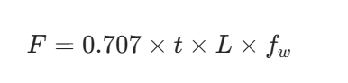
Where t is the throat size of the weld, L is the total weld length, and f_w is the allowable shear stress of the weld material. The 0.707 factor accounts for the geometry of a standard 45-degree fillet weld. Undersizing that throat dimension to save welding time is a common cost-cutting mistake that creates field failures.
For knock-down furniture designed for flat-pack shipping, the challenge shifts to mechanical fasteners. The joint needs enough clamping force to prevent racking under side loads, while being simple enough for non-technical assembly. Tolerances that work fine in a welded assembly can be completely unacceptable when someone’s trying to assemble furniture with an Allen wrench in their living room.
This is where detailed solidworks drafting becomes critical. The difference between a joint that assembles cleanly and one that requires forcing or shimming often comes down to whether the tolerances were specified correctly on the manufacturing drawings.
4. Parametric Families: Building Product Lines, Not Just Products
Commercial furniture rarely exists as single items. You typically need a family: 2-seater, 3-seater, 4-seater versions. Standard height, counter height, bar height options. With arms, without arms, with integrated tables.
Building each variation from scratch is inefficient and creates consistency problems. Instead, smart SolidWorks modeling uses configurations and parametric relationships to drive the entire family from a master model.
Set up the relationships correctly, and you can:
- Lock critical ergonomic dimensions while allowing width or height to vary
- Maintain consistent joint details and hardware across all sizes
- Generate accurate cut lists and assembly drawings for each configuration automatically
- Test structural performance across the full size range with minimal additional modeling work
The result is a product line that looks consistent, feels consistent, and is far more efficient to manufacture and support.
5. Manufacturing Reality: Designing for the Factory Floor
Beautiful, strong, ergonomic furniture that’s too expensive to build won’t survive in the commercial market. That’s where manufacturing-aware modeling becomes essential—thinking like the factory while you’re still designing on screen.
Material optimization means using the thinnest gauge that still meets strength requirements, standardizing hardware across product families, and designing parts to nest efficiently on sheet stock. In SolidWorks, this translates to linking your model dimensions directly to material usage calculations, so you can see the cost impact of design changes in real-time.
Process considerations mean designing tube joints that match your bender’s capabilities, specifying bend radii that your press brake can actually achieve, and positioning welds where a MIG gun can physically reach them. A joint that requires welding in an inaccessible location is a design problem, not a manufacturing problem.
Assembly sequence matters too. Components need to be designed for efficient handling, painting, and packaging. Subassemblies should break down logically for shipping and field assembly. These aren’t afterthoughts—they’re design constraints that need to be built into the 3D model from the beginning.
6. Documentation That Actually Works
Even the most sophisticated 3D model doesn’t communicate everything a manufacturer needs to know. Production-ready furniture design requires comprehensive documentation that translates digital intent into physical reality.
A complete package typically includes a master general assembly drawing showing overall dimensions and bill of materials, detailed part drawings with tolerances and surface finish specifications, weld drawings specifying joint types and sizes, and exploded assembly views showing build sequences.
The goal is documentation so clear that different fabricators, working from the same drawings, produce identical results. When drawings are ambiguous or incomplete, manufacturers fill in the gaps with their own interpretation—which may or may not match your design intent.
7. Why Machine Design Thinking Applies to Furniture
Commercial furniture lives at an interesting intersection—it needs to look good in a showroom but survive like industrial equipment in daily use. That’s why approaching it with a machine design company mindset often produces better results than pure industrial design thinking.
As a machine design company, Asset-Eyes brings the same engineering rigor to a chair joint that we’d apply to a structural frame on industrial machinery. That means:
Building 3D models with manufacturing constraints built in from the start, not retrofitted later. Running structural analysis on load-bearing elements rather than relying on visual judgment alone. Producing detailed, unambiguous manufacturing documentation that suppliers can work from directly. Using solidworks design tools to manage complex assemblies, configurations, and variant families efficiently.
Whether you’re developing commercial seating, workstation systems, or specialized furniture that doesn’t fit standard categories, the engineering process remains consistent: understand the constraints, model them precisely, validate the structure, and document it completely.
This approach works because commercial furniture is essentially a mechanical system that happens to interface with human bodies. Getting both the mechanical engineering and the human factors right requires treating them as integrated constraints, not separate considerations.
Key Takeaways: Making Comfort Manufacturable
Successful commercial furniture design comes down to a systematic engineering approach:
Ergonomics provides hard dimensional constraints that drive structural decisions from the first sketch. Joint design determines whether your product feels solid or develops problems over time. Parametric modeling enables efficient product families while maintaining consistency. Manufacturing intent needs to be built into the 3D model, not added as documentation afterthought. Complete, precise drawings are what separate a design that works on screen from a product that works in production.
If you’re developing commercial furniture or products that need to bridge aesthetic intent with engineering reality, partnering with a design team that understands both human factors and manufacturing constraints can dramatically streamline your path from concept to production.
Contact Us Now:
📞 +91 9840895134
Frequently Asked Questions
1. How does SolidWorks translate ergonomic concepts into precise furniture dimensions?
SolidWorks translates ergonomics into precise dimensions by converting anthropometric data into parametric geometry within the digital model. Engineers build a digital skeleton with invisible reference planes for eye height, lumbar curve location, knee clearance, and arm reach before designing any surfaces. Seat height derives from popliteal height data (floor to back-of-knee measurement), backrest curves follow spinal geometry research, and armrest positioning maps to elbow height ranges when shoulders are relaxed. This creates parametric relationships where changing seat height automatically adjusts backrest angle to maintain proper lumbar support, essentially building a system that understands human anatomy rather than just producing geometry.
2. What anthropometric range must commercial furniture accommodate and why does this create engineering complexity?
Commercial furniture must accommodate the 5th to 95th percentile range of human body dimensions, meaning designs must simultaneously fit someone who is 5’2″ and someone who is 6’2″ without adjustment. This statistical range creates engineering complexity because every ergonomic dimension, from seat depth to armrest height, must work across this entire population. Each comfort requirement starts as human biology data and becomes a parametric dimension with tolerance ranges that the entire structural design must respect simultaneously, like building a house around the plumbing where the constraints are fixed before design begins.
3. Why is parametric modeling essential for ergonomic furniture families in SolidWorks?
Parametric modeling is essential because it enables entire product families to be driven from a single master model while maintaining ergonomic integrity across all variations. Engineers can lock critical ergonomic dimensions while allowing width or height to vary, maintain consistent joint details and hardware across all sizes, and automatically generate accurate cut lists and assembly drawings for each configuration. When relationships are set up correctly, modifying seat depth updates armrest position to keep everything proportional, and changing from a 2-seater to 4-seater maintains the same comfort standards without manual redesign of each variant.
4. What real-world load cases must commercial furniture SolidWorks models handle beyond normal seated weight?
Commercial furniture models must handle comprehensive real-world abuse scenarios including static vertical loads with safety factors for heavier users, horizontal backrest forces simulating aggressive leaning or pushing off to stand, concentrated edge loads from people sitting on armrests or table edges, and dynamic impact loads from chairs being dropped or pushed around. These loads must follow clear paths from contact points through the structure to the floor, like water flowing downhill. Any bottleneck or sharp turn in that load path creates stress concentrations that SolidWorks Simulation reveals as red zones requiring design attention before physical prototypes are built.
5. Why are furniture joints the most critical engineering element and how are they calculated?
Joints are where loads concentrate and failures begin in commercial furniture because they interrupt the natural load flow through the structure. For welded steel frames, fillet weld shear capacity follows the precise formula:
$$P = 0.707 \times t \times L \times f_w$$
where t is the throat size of the weld, L is the total weld length, and f_w is the allowable shear stress of the weld material. The 0.707 factor accounts for the geometry of a standard 45-degree fillet weld. Undersizing throat dimensions to save welding time is a common cost-cutting mistake that creates field failures. For knock-down furniture designed for flat-pack shipping, mechanical fasteners must provide sufficient clamping force to prevent racking under side loads while remaining simple enough for non-technical assembly with basic tools.
6. How does SolidWorks Simulation validate furniture structural integrity before physical prototypes?
SolidWorks Simulation allows engineers to apply virtual loads to digital models and watch stress patterns develop in real-time, revealing where forces actually travel through the structure and where dangerous concentrations form. A joint that appears perfectly reasonable in the 3D model might light up red under analysis, showing stress concentrations that need design attention. This virtual testing catches structural problems while they remain digital and affordable to fix, before expensive physical prototypes are fabricated and tested. Engineers can identify load path bottlenecks, optimize joint geometry, verify weld sizing adequacy, and confirm designs handle the full range of abuse scenarios.
7. How do SolidWorks configurations enable efficient commercial furniture product family development?
SolidWorks configurations allow entire product families, including 2-seater through 4-seater versions and standard through bar-height options, to be driven from a master parametric model instead of building each variant from scratch. This approach locks critical ergonomic dimensions while allowing width or height to vary, maintains consistent joint details and hardware across all sizes, automatically generates accurate cut lists and assembly drawings for each configuration, and enables structural performance testing across the full size range with minimal additional modeling work. The result is visual and performance consistency across the product line with dramatically reduced development time and documentation effort.
8. What manufacturing constraints must be built into furniture 3D models during design rather than addressed afterward?
Manufacturing constraints must be integrated from the design phase to ensure cost-effective production. This includes material optimization using the thinnest gauge that meets strength requirements, standardizing hardware across product families, and designing parts to nest efficiently on sheet stock. Process considerations mean designing tube joints that match actual bender capabilities, specifying bend radii achievable by available press brakes, and positioning welds where MIG guns can physically reach them. Assembly sequence must account for efficient handling, painting, and packaging, with subassemblies breaking down logically for shipping and field assembly. Joints requiring welding in inaccessible locations represent design problems, not manufacturing problems.
9. What documentation package does production-ready commercial furniture require beyond 3D models?
Production-ready furniture requires comprehensive documentation that translates digital intent into physical reality so different fabricators produce identical results. The complete package includes a master general assembly drawing showing overall dimensions and complete bill of materials, detailed part drawings with tolerances and surface finish specifications, weld drawings specifying joint types and sizes, and exploded assembly views showing build sequences. When drawings are ambiguous or incomplete, manufacturers fill gaps with their own interpretation, which may not match design intent and creates inconsistent product quality. The standard is documentation so clear that any qualified fabricator can work directly from the drawings without requiring additional engineering support.
10. How does Asset-Eyes approach commercial furniture development as an integrated engineering challenge?
Asset-Eyes treats commercial furniture as a mechanical system that interfaces with human bodies, requiring simultaneous integration of ergonomic constraints, structural engineering, and manufacturing requirements rather than treating them as separate considerations. Their machine design company approach applies the same engineering rigor to chair joints that they would apply to structural frames on industrial machinery. This means building 3D models with manufacturing constraints from the start, running structural analysis on load-bearing elements rather than relying on visual judgment, producing detailed unambiguous manufacturing documentation that suppliers can work from directly, and using SolidWorks design tools to manage complex assemblies and variant families efficiently. This systematic engineering process ensures designs that work aesthetically, survive commercial use, and can be manufactured consistently and cost-effectively throughout the product’s lifecycle.