Explore our advanced solutions for HVAC, Mechanical, Electrical, and Automation design. Get in touch today

Special Purpose Machine Design

Fully custom-engineered automated systems, complex kinematics, and process tooling in compliance with ISO 12100 & ISO 13849-1.

Specialized Engineering Services

Machine Systems Design & Requirements

Special purpose machine design starts with defining process requirements and building an integrated machine system around them. Asset-Eyes combines mechanical, structural, safety, and operational design into a single coordinated system, starting from the client's specific process and throughput needs rather than a generic machine template.
Integrated Machine System Development
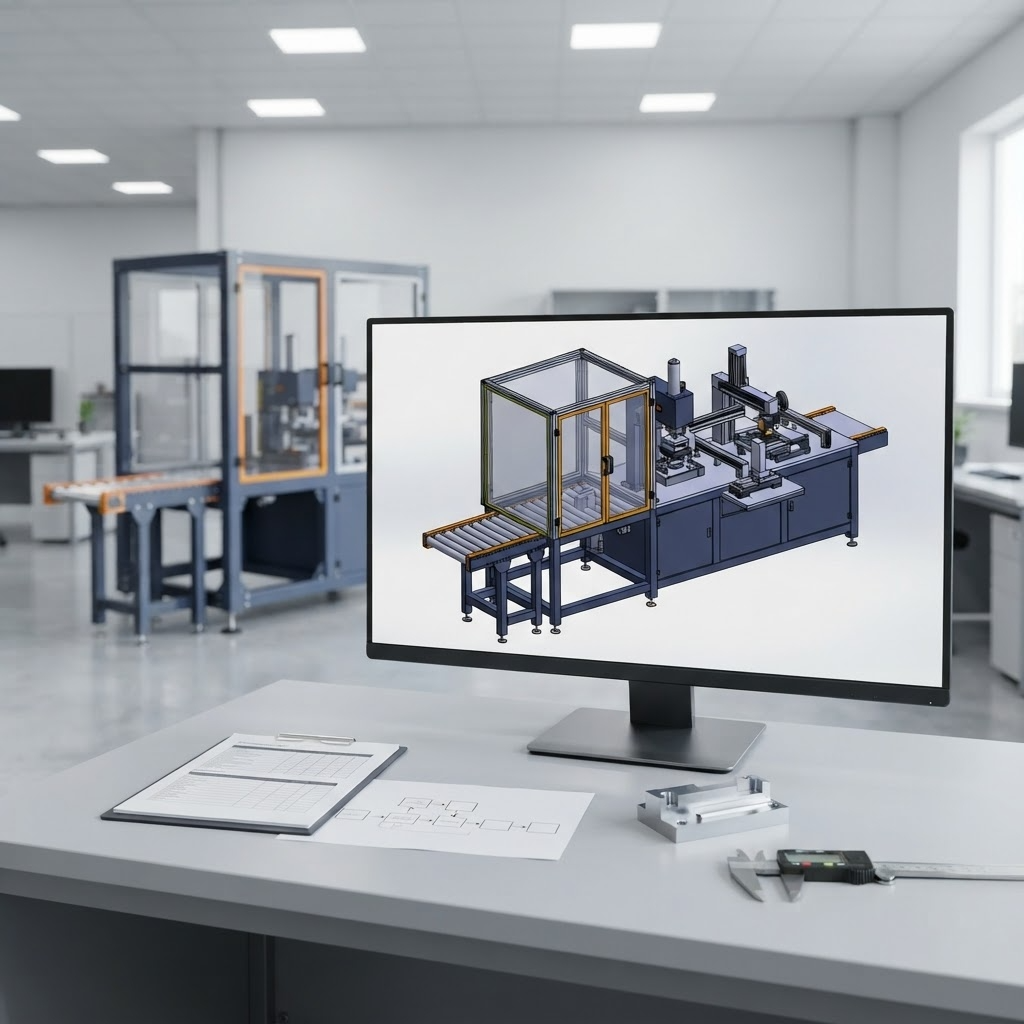
Asset-Eyes develops integrated machine systems that combine mechanical, structural, safety, and operational design within a single 3D assembly, built in SolidWorks and AutoCAD. This integration ensures that safety systems, structural elements, and mechanical function are designed together rather than added on separately. Asset-Eyes uses this combined approach so the machine functions as one coordinated system from the earliest design stage.
Machine Requirement Specification
Asset-Eyes works collaboratively with clients to specify machine requirements, covering process requirements, throughput targets, operational conditions, and system integration needs. This specification stage sets the technical baseline that all downstream design decisions are measured against. Asset-Eyes treats this collaborative step as the foundation for the rest of the machine design process.
Machine Systems Design & Requirements

Motion & Drive System Engineering

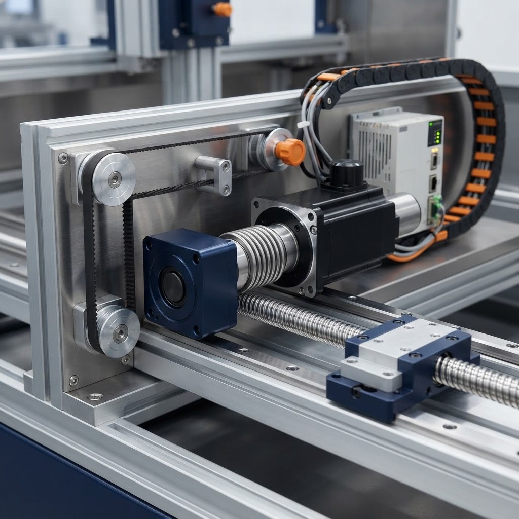
Motion and drive system engineering covers the kinematic design and drive sizing work that determines how a special purpose machine actually moves. Asset-Eyes designs motion systems and validates drive components against real operating conditions, not just theoretical load figures.

Kinematic Design and Motion System Engineering
Asset-Eyes engineers kinematic design and motion systems for cam-linkage mechanisms, linear guides, rotary index tables, and custom transfer systems, based on validated motion analysis. This ensures the mechanism selected actually achieves the required motion profile before it's built. Asset-Eyes validates each motion system's behavior analytically before committing to a final mechanism design.
Drive System Sizing and Validation
Asset-Eyes sizes and validates drive systems, including servo, ball screw, rack-and-pinion, pneumatic, and hydraulic systems, to operate within continuous operating limits. This validation confirms the drive system can sustain production-level duty cycles without premature wear or failure. Asset-Eyes matches drive system selection to the specific motion and load requirements identified during kinematic design.
Motion & Drive System Engineering

Structural, Interface & Ergonomic Design

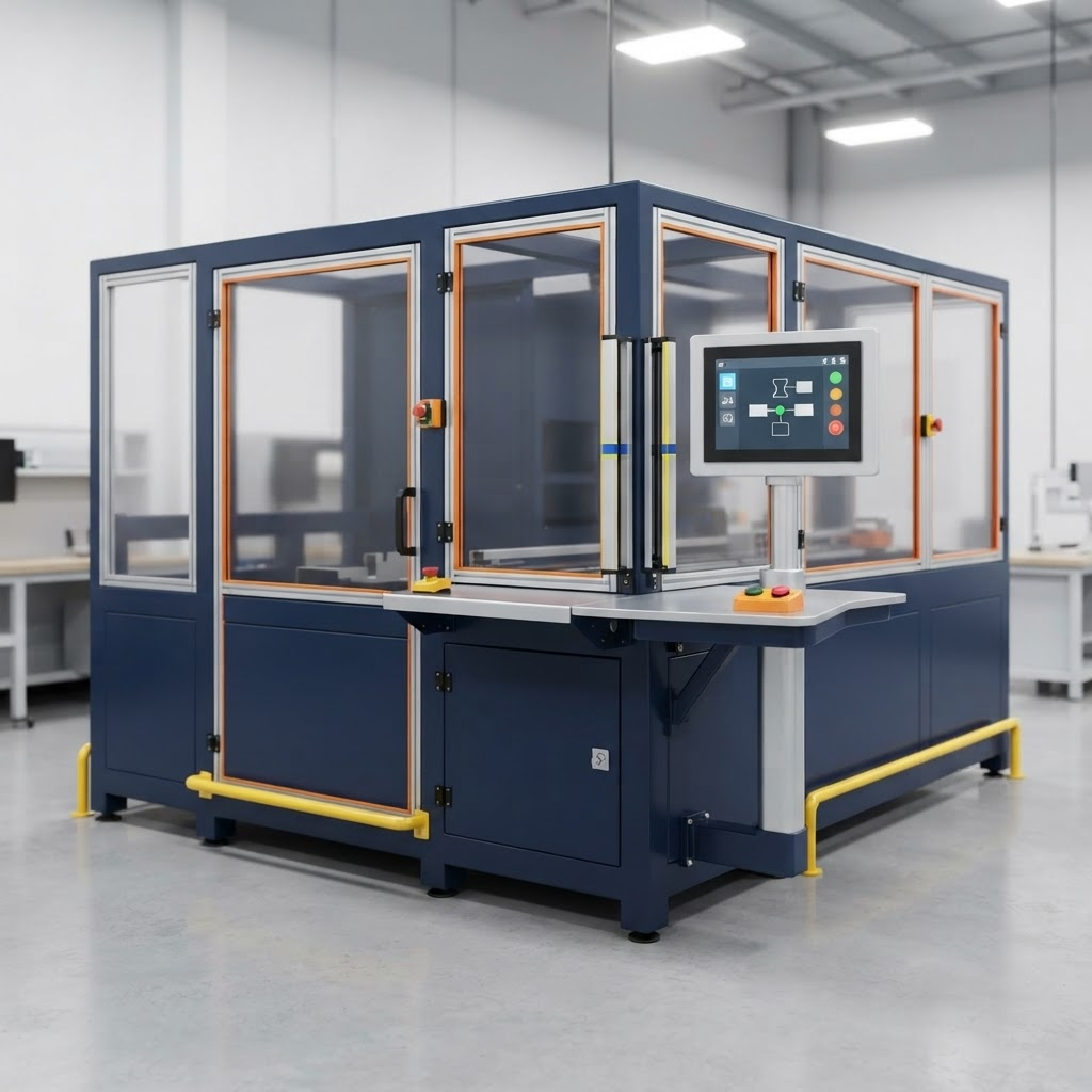
Structural, interface, and ergonomic design covers the machine's physical frame, operator interaction points, and human factors considerations. Asset-Eyes designs these elements together so the machine holds dimensional accuracy under load while remaining accessible and safe for operators and maintenance staff.

Structural Framework Design
Asset-Eyes designs structural frameworks with bending, shear, and deflection analysis to maintain critical dimensional accuracy under operating loads. This analysis ensures the frame doesn't deflect enough to compromise the machine's precision during operation. Asset-Eyes builds this structural validation into the frame design before it moves to fabrication.
Tooling Interface and Human-Machine Interaction Design
Asset-Eyes designs tooling interfaces and human-machine interaction points, including controls, loading stations, and maintenance accessibility. This design work determines how operators and technicians physically interact with the machine during normal use and service. Asset-Eyes positions these interfaces based on operational workflow and maintenance access needs.
Ergonomic Work-Envelope Development
Asset-Eyes develops ergonomic work envelopes with optimized reach zones, visibility requirements, and maintenance clearances. This work envelope design reduces operator strain and ensures critical components remain visible and reachable during operation. Asset-Eyes factors these ergonomic requirements into the machine layout alongside its structural and interface design.
Structural, Interface & Ergonomic Design

Documentation & Commissioning

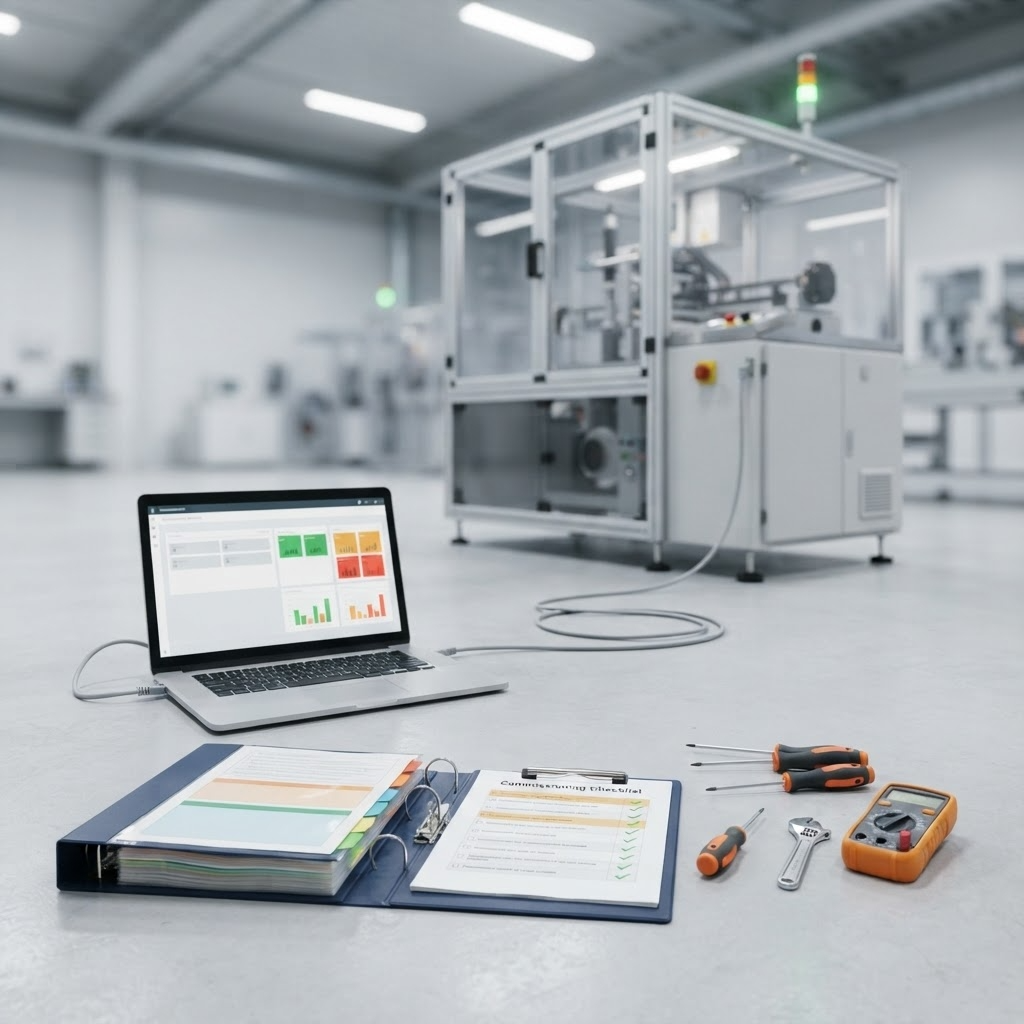
Documentation and commissioning covers the engineering package and performance work that carries a special purpose machine from design into production-ready operation. Asset-Eyes produces complete documentation and supports commissioning so the machine reaches target throughput with minimal post-installation modification.

Complete Engineering Documentation Package
Asset-Eyes develops complete engineering documentation, including 3D assembly models, GD&T-compliant fabrication drawings, assembly instructions, and bills of materials, as a package supporting fabrication, assembly, commissioning, operation, and maintenance activities. This documentation gives every downstream team, from fabricators to maintenance staff, a single accurate reference. Asset-Eyes builds this package directly from the finalized machine design rather than as a separate documentation exercise.
Commissioning Performance Engineering
Asset-Eyes engineers commissioning performance with a focus on achieving target throughput, reducing on-site modifications, and accelerating production release. This work addresses issues before they surface during live commissioning, rather than troubleshooting them after installation. Asset-Eyes ties commissioning performance directly back to the validated motion, drive, and structural design work completed earlier in the project.
Documentation & Commissioning
Engineering Tools

Machine Design Engineered To Perform

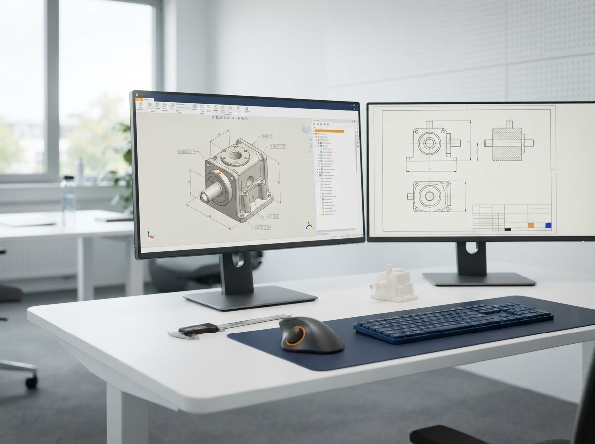
Automation machine design is exclusively a 3D process at Asset-Eyes. We utilize industry-leading CAD environments to guarantee compatibility and seamless translation to the factory floor.
Engineering Tools
1

SOLIDWORKS

SOLIDWORKS is used to develop mechatronics systems from beginning to end. At the initial stage, the software is used for planning, visual ideation, modeling, feasibility assessment, prototyping, and project management. The 3D modeling software is then used for design and building of mechanical, electrical, and software elements.
2

AutoCAD

AutoCAD is our primary design tool for controls engineering (electrical, fluid power) and the latest software versions are always utilized. We use the AutoCAD Electrical Toolset for the creation of controls drawings. The use of AutoCAD Electrical Toolset improves efficiency, reduces errors, and essentially creates a smart design package.
3

Additional Software Competence

For manufacturers standardizing on alternative platforms, our team maintains full functional design workflows in Autodesk Inventor and PTC Creo Parametric, ensuring full design history, parametric constraints, and drawing format compliance.

Resources

Let's Talk About Your Engineering Needs

Tell us where your team needs more capacity. We'll show you how our engineers can help.